Just some general questions about remaking something from the past

Status
Not open for further replies.

Audioguru

Joined Dec 20, 2007
11,248
Half-decent car speakers already have a woofer and tweeter, a few are three-way with an added midrange speaker. They have a built-in crossover network (a series capacitor for the tweeter).
The TDA7396 amplifier produces 33W into 2 ohms with a 14.4V supply or 40W with a 16V supply. The size of the heatsink must be 1.6 times the size of the one good for a 4 ohm speaker.

Crutchfield sell two 6" x 9" 2 ohm speakers, one is two-way (60W) for $79.99 a pair and the other is three-way (50W) for $89.99 a pair. They have almost no detailed audio specifications.
Parts Express do not list the impedance of most of their 6" x 9" car speakers so I think they are all 4 ohms.
 

shortbus

Joined Sep 30, 2009
10,049
No shortbus "I Cheated" (?) I opened the PCB layout and worked from there.
Kind of thought that's what you did. The whole idea of all of the circuit/PCB software's out there is to make tings in schematic first. By doing that changes may be made without much trouble, by changing parameters in the PCB section, not having to start over every time.

But making a schematic up doesn't change the space between the IC's pins
You should never run "power" traces between the IC pins. Under things like resistors or caps or other discrete components is usually OK.
 

Thread Starter

Berzerker

Joined Jul 29, 2018
623
No power traces under the IC, their out front of it. I have one speaker output going through or in between it though.
Have another problem I'm working on now with it. When your in the PCB layout you know how you hover over a pad and it will show you the path from end to end. I have two capacitors that only go from the pad to the capacitor and then stops. In other words it doesn't go through the capacitor to the other end. why is this?
Take that back one is a resistor
 
Last edited:
No power traces under the IC, their out front of it. I have one speaker output going through or in between it though.
Have another problem I'm working on now with it. When your in the PCB layout you know how you hover over a pad and it will show you the path from end to end. I have two capacitors that only go from the pad to the capacitor and then stops. In other words it doesn't go through the capacitor to the other end. why is this?
Take that back one is a resistor
Because the software is highlighting a NODE. The node does not extend through a component. If it does, then what is the point of the component? Components cause a signal to behave differently. If nothing is different on each side of a component, you may as well leave off the component and put a copper trace where the component was.
 

Thread Starter

Berzerker

Joined Jul 29, 2018
623
Sonoran said:
Because the software is highlighting a NODE. The node does not extend through a component. If it does, then what is the point of the component? Components cause a signal to behave differently. If nothing is different on each side of a component, you may as well leave off the component and put a copper trace where the component was.
Now that was a great explanation. Thanks Sonoran.
 

Thread Starter

Berzerker

Joined Jul 29, 2018
623
Sonoran said:
I have looked at them Sonoran but then there's shipping cost. If I ship from inside the US it's sometimes free and most of the time if there is a charge it's less than $5.00 - $7.50. And those are 6 1/2" round, for now I want to test with 6x9. But don't think I haven't thought about door mount applications.
AG said:
Crutchfield sell two 6" x 9" 2 ohm speakers, one is two-way (60W) for $79.99 a pair and the other is three-way (50W) for $89.99 a pair. They have almost no detailed audio specifications.
I did look at them AG and I have their page in my favorites.
 

shortbus

Joined Sep 30, 2009
10,049
No power traces under the IC, their out front of it. I have one speaker output going through or in between it though.
I would consider that a power trace. Not power as in providing power to the circuit, but, power out of the circuit to the speaker. Any trace that has a high current on it would be a "power" trace.
 

Thread Starter

Berzerker

Joined Jul 29, 2018
623
shortbus said:
I would consider that a power trace. Not power as in providing power to the circuit, but, power out of the circuit to the speaker. Any trace that has a high current on it would be a "power" trace.
I understand shortbus but I can't make something that is humongous on the bottom of the speaker and look awful. It runs right beside the other speaker output and is nowhere around the DC inputs. space is limited in the design. the schematic on the datasheet has something close to it.
 
I understand shortbus but I can't make something that is humongous on the bottom of the speaker and look awful. It runs right beside the other speaker output and is nowhere around the DC inputs. space is limited in the design. the schematic on the datasheet has something close to it.
Defying the laws of physics is often requested by designers for the sake of aesthetics.
 

Thread Starter

Berzerker

Joined Jul 29, 2018
623
I have looked in Diptrace and all over the internet about trace thickness. Nothing I can find anywhere tells about how to input the thickness.
Everything is about width (?). I know there has to be a way to tell it (diptrace) or the PCB manufacturer how thick you want it.
And do they only need the gerber files and the drill files or is there something else I need to export?
And I read some of the post on here about PCB manufacturer choices. I want to ask who you actually use and have used and the best one you've found so far.
 
Last edited:

ebeowulf17

Joined Aug 12, 2014
3,307
I have looked in Diptrace and all over the internet about trace thickness. Nothing I can find anywhere tells about how to input the thickness.
Everything is about width (?). I know there has to be a way to tell it (diptrace) or the PCB manufacturer how thick you want it.
And do they only need the gerber files and the drill files or is there something else I need to export?
Sorry, l thought other people's replies had already touched on that, but maybe not. The copper thickness may be included as a note in your drawings, but it's not an integral part of the board files themselves. It's part of the ordering process.

The raw PCB stock they start with in order to make your boards already comes with copper on it. Different thickness means starting with a different raw stock piece. When you get quotes online, you can quote the same design in various copper thicknesses.

Also, just to be clear, the thickness is for all traces on that layer - it doesn't vary on a trace by trace basis.

It's like if you were getting a piece of steel laser cut, you could choose to get it cut out of 12 gauge or 1/4" steel, but the laser pattern would be the same either way, and the steel thickness wouldn't vary throughout the part.
 

Thread Starter

Berzerker

Joined Jul 29, 2018
623
Got it ebeowulf. I posted above about who you "actually" use as a PCB supplier. I've read the posts here and everyone says this one or that one.
I want to know who you or anyone else uses.
 

ebeowulf17

Joined Aug 12, 2014
3,307
Got it ebeowulf. I posted above about who you "actually" use as a PCB supplier. I've read the posts here and everyone says this one or that one.
I want to know who you or anyone else uses.
For several personal projects and for low cost prototyping on one work project, I used ALLPCB. I was really happy with them on all those jobs.

For production quantities on work projects, l don't actually know who the PCB houses have been. We contract out our assembly work, because electronics are just a small part of our machine, and soldering isn't our strong suit. The assembly house gets bids and sources PCBs to our specs, and they act as the middle man for us. We never work directly with the PCB manufacturers.

I have no idea what they're like for big orders, but for the handful of 10-20 piece orders I've done through ALLPCB, they've been great.
 

shortbus

Joined Sep 30, 2009
10,049
Aaaa, aesthetics. Beauty is in the eye of the beholder. read an article and some post. although it's not advised if you can get away from it, it is not unheard of and often done.
https://www.avrfreaks.net/forum/routing-pcb-traces-under-ic-bad-idea

https://electronics.stackexchange.c...ng-signal-traces-under-components-a-good-idea
And like my earlier post you missed the key words in your links, "signal traces", not power/current traces. There is a difference. And to through another thing out there, not all traces on a PCB have to be traces. Sometimes it is easier or even better to use a "jumper", a separate wire soldered between two pads on the PCB. Especially when you need a heavier/wider trace to get the job done.
 

shortbus

Joined Sep 30, 2009
10,049
I understand shortbus but I can't make something that is humongous on the bottom of the speaker and look awful. It runs right beside the other speaker output and is nowhere around the DC inputs. space is limited in the design. the schematic on the datasheet has something close to it.
So these speakers will be open on all side?? Not in a package tray opening like was done when the originals were around?? You do know that may bring AG down on you again, don't you? Even the worst speaker sound better in an enclosure, even if it is just the trunk of a car.
 

Thread Starter

Berzerker

Joined Jul 29, 2018
623
shortbus said:
So these speakers will be open on all side?? Not in a package tray opening like was done when the originals were around??
Yes except for the cover on the bottom to keep peoples fingers out of it and a guard around the heatsink. It will have air space around everything.
shortbus said:
And like my earlier post you missed the key words in your links, "signal traces", not power/current traces. There is a difference. And to through another thing out there, not all traces on a PCB have to be traces. Sometimes it is easier or even better to use a "jumper", a separate wire soldered between two pads on the PCB. Especially when you need a heavier/wider trace to get the job done.
You know that's a great, no Brilliant idea. I could just use some 12 or 14 guage wire and wont have to worry about going through anything.
shortbus said:
You do know that may bring AG down on you again, don't you? Even the worst speaker sound better in an enclosure, even if it is just the trunk of a car.
Aaah, I can handle AG. he may bark loud but I don't think he'll bite. :rolleyes:
 

Thread Starter

Berzerker

Joined Jul 29, 2018
623
Sonoran said:
Google "trace width calculator" any you'll get many options to tell you that you'll need 0.080" trace width for a 4A load if using 1 oz/square foot copper PCB.
Here is one, there are many more...
https://www.4pcb.com/trace-width-calculator.html
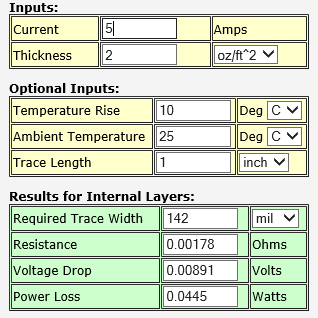
I'm still looking at trace width. Sonoran came up with .080 (?) it says 142 wide @ 2oz, 94.4 @ 3 oz and if you enter 4oz you get 70.8 wide. I don't want to under do it, I'd rather be on the safe side. trying to figure where .080 came from ?

AG said almost 5 amps.
 

Audioguru

Joined Dec 20, 2007
11,248
The enclosure for the rear of a speaker needs to be designed for the detailed spec's of the speaker. But car speakers do not have any detailed spec's, they are simply mounted on the rear shelf then the entire car trunk (boot?) is the enclosure. The enclosure prevents sound waves from the rear of the speaker from cancelling low frequency sound waves from the front. If the enclosure is too small then there will be a peak in the upper bass and the speaker will sound boomy like a one note bongo drum.
 
Status
Not open for further replies.
Top