Just some general questions about remaking something from the past

Status
Not open for further replies.

ebeowulf17

Joined Aug 12, 2014
3,307
Perhaps I used the wrong terminology before: "Saturated" vs "Active" in the textbook on this site. Start on this page and read the next three or four in order to get a basic intro, including the different applications of a BJT:
https://www.allaboutcircuits.com/textbook/semiconductors/chpt-4/bipolar-junction-transistors-bjt/

Here's another good tutorial. This one introduces the different modes of operation much earlier, and a little more clearly:
https://www.electronics-tutorials.ws/transistor/tran_1.html

For what it's worth, when it comes to learning electronics online, there is a LOT of bad information out there. I would read very critically when getting opinions from most forums and Q&A sites.

The textbook/tutorial sections of this website and the www.electronics-tutorials.ws/ site listed above are both reliable.

This forum and electro tech are both quite good, and you can also sometimes find useful info at stack exchange, although I've seen plenty of wildly inaccurate answers there go unchallenged, so be careful what you believe there. Look for consensus among many, not just one response.

I would avoid instructables like the plague, and only use the Arduino forums for microcontroller-specific info, not general electronics knowledge. Any other site where people are "hacking" or "making" should also be treated with skepticism and caution.

It's not that there isn't good info out there, but it's hard to tell the good from the bad if you don't already know what you're doing. If you just read the results of any ol' Google search, you'll get lots of conflicting information on just about any electronics question. So, stick to reliable sources whenever possible.
 

Thread Starter

Berzerker

Joined Jul 29, 2018
623
I try to divide my day up like you would in school on it. some reading and video's here and some other places till my eyes tire from it then I get the amp and look it over taking the advice of shortbus.
shortbus said:
Instead of concentrating at this stage on what components do and how they work, would it make more sense to learn what the total package did?
I look at how the +VDC could have flowed and I one I took all the parts off to find out what they were and test. I have found a 12VDC wall transformer I connect to the parts and the one still intact. when I don't understand I jump on that and search it (no matter where). but you don't just get two terms on this. There are bjt, linear, off/on. semiconductor, the difference in the flow of PNP and NPN, filling holes and electrons. It's a little confusing to me at least but I read on and get a bit smarter on it each day.

Edit: must have been posting this while you were posting that
 

Audioguru

Joined Dec 20, 2007
11,248
Simply learn what a transformer does, how transistors work and what a resistor does.
Learn the simple Ohms Laws and the Power Laws.
Learn about AC peak audio voltages and currents.
Learn how to read datasheets.
Calculate what spec's the parts need, find suitable parts and order them.
Put the parts together and test the results.
Then learn the details by fixing your mistakes.
 

Thread Starter

Berzerker

Joined Jul 29, 2018
623
I think you just helped me figure out what I wasn't understanding about how it worked Audioguru and what the transformer on it was for.
Went looking up what voltage a car head unit puts out and am I correct it's VAC? So the 12VDC would only turn the transistor to (ON) and then VAC would drive the speakers itself? Next question would be: you "can" have two different types of voltage on a transistor? I tested the converter or transformer on 12VDC and nothing (no reading) with the meter. If it's working on VAC then I know why now. And am I also correct that the VAC coming from the head unit is very low, like 1 to 2 volts.
 

Audioguru

Joined Dec 20, 2007
11,248
A modern car head unit (radio) is designed to drive 4 ohm speakers to about 14W with bridged class-AB dual amplifiers per channel.
The car battery is about +13.2VDC and the output from each amplifier is biased at half that at (13.2V/2=) +6.6VDC so that it can swing symmetrically up and down with AC audio. The class-AB output transistors have voltage losses so their output voltage swing is from +1.2V to (13.2V - 1.2V=) +12V for a maximum total voltage swing of 10.8V peak-to-peak which is 3.8V RMS AC. The volume control on the radio can turn it down to 1 to 2V if you want. The maximum undistorted power in a 4 ohm speaker is (3.8VAC squared/4 ohms) x 4= 14.4W.

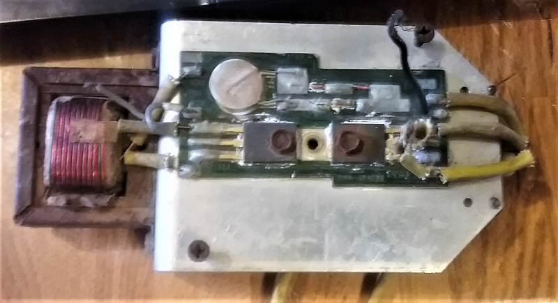
The mindblower speaker originally had a center-tapped voice coil then later an ordinary speaker and a maybe a center-tapped output transformer.
Text with errors about +6.6VDC has been deleted.

The input transformer isolates the DC on the outputs of the car radio from the bases of the power transistors. The secondary of the input transformer drives the bases of the power transistors with AC audio and has a DC bias voltage so that the transistors have their collectors at half the supply voltage.

Transformers stepup or stepdown AC voltages.
 
Last edited:

Thread Starter

Berzerker

Joined Jul 29, 2018
623
Soooo; I'll take that as a (yes). The part about the 6.6VDC I can't see though. The 12VDC connects straight to the base of the transistor so there is no 6.6 volts. If the audio input is VAC the transformer would have to be a step up transformer. With the old version there was no transformer to turn it from a three wire into a two wire speaker, again this was later added to make it do so. So the only way it could be amplified was through the VAC transformer. Now the step up transformer should determine how many watts it puts out correct?
 

Audioguru

Joined Dec 20, 2007
11,248
We did this already.
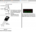
Again, you wrongly show the pins on a low power European transistor, not the pins on an American power transistor.
the collector gets the hottest so it is the metal base and middle pin.
 

Attachments

Audioguru

Joined Dec 20, 2007
11,248
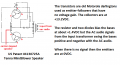
The transistor's collectors connect to +13.2VDC.The emitters connect to the speaker or the output transformer and swing symmetrically up and down. You are correct, I was wrong. The bases are not biased at half the supply voltage. Instead they are biased with the resistor and two diodes at +1.4VDC so that the emitters are at 0VDC. The signal from the input transformer causes the base voltages to swing up and down that causes the emitters and ends of the speaker coil to also swing up and down with lots of current gain.

The transistors are emitter-followers so they have no voltage gain. 5VAC in at the base produces about 4.9V at the emitter.
I found the patent again:
 

Attachments

Thread Starter

Berzerker

Joined Jul 29, 2018
623
Thanks AG you had me scratching my head. it was like everything I thought just went Poof. I have a copy of that diagram and I'm going to look at it real hard today. Now that we have determined it is a transformer I got thinking "I know, I know" I can just hear you say crap here we go again AG. So this thing is just a AC transformer in between the speaker input and the speaker output (basically). The transistors only turn it Off and On (again basically). The input and output voltage on the transformer determine the watts so this can be changed to give it more wattage.
Now my next question: The floating (or dual should I say) ground was used to handle the difference of the VAC and VDC being mixed on the same board right? Cos the grounds all go to the same wire that hooks to the chassis. And I know you can't mix AC and DC this would only end in KA-Boom. Another question: Lets say that the capacitor is no longer made (It isn't) I can still put the values in Diptrace and see if it works correct? or try another to see if it can be replaced? same with different transformers? Then this will leave me with only two components to figure out how they work.
 
Last edited:

Audioguru

Joined Dec 20, 2007
11,248
The transistors in a digital computer turn on and off. The transistors in an analog amplifier turn on only as much as the input audio signal drives them, linearily.

The transformers boost the audio signal voltage and the darlington transistors used as emitter-followers have no voltage gain but they do have a high current gain. Power is voltage times current so a transformer by itself is not an amplifier, the current also must be boosted by the emitter-follower Darlington transistors. The simple circuit has no negative feedback that is used in all modern amplifiers so its distortion is fairly high.

The schematic in the patent does not show a capacitor which is probably parallel with the battery supply input. Capacitors are made with a value similar to whatever it used and the same voltage rating.

The special audio transformers are not used and are not available today and were custom-made for the MindBlower speaker.
 

shortbus

Joined Sep 30, 2009
10,049
The special audio transformers are not used and are not available today and were custom-made for the MindBlower speaker.
That's why I suggested for him to find a way of doing this, duplicating the effect the original had, using modern components. But have to say I never had any interaction with these speakers, so don't know how they sounded or what the circuit was supposed to do.
 

Thread Starter

Berzerker

Joined Jul 29, 2018
623
I understand but once I figure out how it worked I can put newer components together and do the same thing right? their has to be an audio amplifier (transformer) out there that can take it's place or use a couple (or so) of components to do it.
Edit: shortbus you were reading my mind
 

Audioguru

Joined Dec 20, 2007
11,248
You didn't hear me. Custom made transformers like used in the Mindblower speaker are not available today.

Audio transformer manufacturers and distributors still stock audio transformers to replace the ones in old vacuum tube guitar amplifiers. Sure, use vacuum tubes and replace them each year or sooner. Power them from a few hundred volts. The people who like RETRO might buy them.

To increase the power of a car audio amplifier to be higher than about 14W per channel into 4 ohm speakers, 2 ohms speakers can be used or a power supply booster can change the +14.4V to +40V or more, then a higher power amplifier can be made from a modern amplifier IC.

Crutchfield sells hundreds of types of car speakers and show 2 ohms 6" x 9" at $ 79.99US a pair. Without boosting the power supply voltage then a TDA8566 car radio amplifier IC will produce 30W per channel into 2 ohms at low distortion. It will not have the distortion, missing bass and poor highs of an old MindBlower speaker.

Beware of speaker and amplifier power ratings. Frequently they make the numbers higher by using horribly high distortion and "maximum" or "peak" watts that are simply double the real number of watts at very high distortion levels. My power numbers are real watts at low distortion.
 

Thread Starter

Berzerker

Joined Jul 29, 2018
623

Thread Starter

Berzerker

Joined Jul 29, 2018
623
I want you to know I really appreciate you, shortbus, ebeowulf, Mrchips and if I've forgotten any one please forgive me this is off the top of my head. I have gotten further in a couple of weeks than I thought I would. I figured it would take around 6 to 8 months when I first posted. I'm pretty close to understanding it. One of my good trades is hunting stuff down and if I can't find an original I'll find something to replace it. I do understand the cost might not be worth the effort or make my idea non realistic. To me at least I tried.
My Dad said:
I can't never could.....I "CAN" makes a man
I took this to mean don't give up till you know it's no longer an option, then regroup and try another way. Yes there are two different transformers and as soon as I get the hang of Diptrace and be able to portray what I see accurately enough for you guys to understand, I will do so. I did get my photoshop back working (had to reload it) so I can place a pic of it but would like to post both at the same time.
And I did forget but thank you bertus
Edit: Got it and reading now bertus "THANKS"
 

Audioguru

Joined Dec 20, 2007
11,248
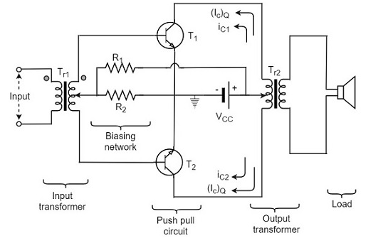
The Tutorials Point amplifier uses common-emitter transistors that produce voltage gain and current gain unlike the Darlington emitter-followers in the MindBlower speaker that had no voltage gain.

Speaking of antique amplifiers, Philips had an amplifier in 1955 (63 years ago!) powered from 12V and it used an output transformer. The designers desperately avoided using an input (or driver) transformer. The output power was a whopping 0.05W.
 

Attachments

Thread Starter

Berzerker

Joined Jul 29, 2018
623
"THAT'S IT" bertus almost to a tee. A few differences but that's it.
bertus posted link:

The only thing is the ground side is different but that just might be me looking at it wrong or not understanding what I see "you pick"

But at the very bottom it says:
below said:
The transformers are bulky and costly.
 
Status
Not open for further replies.
Top