Is this just a Detector and an Integrator? How does it work?

Thread Starter

trmz

Joined Jun 28, 2025
12
Hello there!

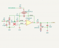
I am new to electronics, and I am trying to understand how this circuit works.

Before it are 3 stages of Active Bandpass Amps.

1751124296836.png


The whole circuit is trying to extract some AM signal from an antenna. I have already found how the Bandpass worked in the circuit, but I can't find documents on this design...

If anyone has some info on this that I could read or if it’s easy to tell me because I'm trying to electronics on my own.

Thanks
 

crutschow

Joined Mar 14, 2008
38,316
It's not an "Active Bandpass Amps".
It's a diode detector followed by an op amp integrator followed by a passive low-pass filter.

And that circuit does not work since the op amp integrator has no DC feedback .
The op amp output will go to a rail voltage and stay there.

Where did you get that circuit?
 
Last edited:

Thread Starter

trmz

Joined Jun 28, 2025
12
It's not an "Active Bandpass Amps".
It's a diode detector followed by an op amp integrator followed by a passive low-pass filter.

And that circuit does not work since the op amp integrator has no DC feedback .
The op amp output will go to a rail voltage and stay there.

Where did you get that circuit?
I mean, before this there is an Active Bandpass Amp.

So I knew there had to be a detector and an integrator from what I read, but I didn't know where they are, and I didn't see the low-pass filter (now I do; I just don't see why there is a diode also connected from VSSA to the output).

This is from the receptor part of a graphic tablet called Project Patchouli:
https://patchouli.readthedocs.io/en/latest/Impl/EDR_v2/

I just can't find how diode detectors work...

And what is the DC feedback?

Thank you very much for the reply !
 
Last edited:

Thread Starter

trmz

Joined Jun 28, 2025
12
Hi trm,
Sorry, but I do not use kicad.
Can you post what the original designer stated as its purpose.?
E
1751197816442.pngCapture d’écran 2025-06-29 à 1.50.29 PM.png

basically this is the part from Amp to Integrator,
it takes from the coils a signal sent from the pen (at 500 to 750kHz) and tries to amplify and clean it.
 

MrChips

Joined Oct 2, 2009
34,628
Is it an integrator or low pass filter, or both?

What is the frequency response graph of a low pass filter?
What is the frequency response graph of an integrator?

We tend to be familiar with an RC low pass filter that looks like this.
1751198242453.png

But isn’t this also an integrator?
 

Thread Starter

trmz

Joined Jun 28, 2025
12
Is it an integrator or low pass filter, or both?

What is the frequency response graph of a low pass filter?
What is the frequency response graph of an integrator?

We tend to be familiar with an RC low pass filter that looks like this.
View attachment 351846

But isn’t this also an integrator?
Uh, are you asking this to me or the others? Because I have no idea if it is also an integrator.
What I can say is that in post #1, this is a combination of a detector integrator and low pass, as crutschow said in post #2, and I figured out where the integrator and low pass are. However, I don't understand how the diode detector works at all.
 

ericgibbs

Joined Jan 29, 2010
21,390
hi trm,
That added MOSFET makes the design intention more clear.
The signal after passing through the BPF is rectified at the input of the integrator, the timed integration period is controlled by a microcontroller using the MOSFET as the discharge path.
The smoothed voltage signal is also sampled using an ADC.
E
EG 1565.png
 

Thread Starter

trmz

Joined Jun 28, 2025
12
hi trm,
That added MOSFET makes the design intention more clear.
The signal after passing through the BPF is rectified at the input of the integrator, the timed integration period is controlled by a microcontroller using the MOSFET as the discharge path.
The smoothed voltage signal is also sampled using an ADC.
E
View attachment 351852
Hi eric!
Thank you for that information! I didn’t understand those and thought they were for debugging! Thank you very much i will look into the microcontroller script and documentation!
Have a great day
 

MrChips

Joined Oct 2, 2009
34,628
Uh, are you asking this to me or the others? Because I have no idea if it is also an integrator.
What I can say is that in post #1, this is a combination of a detector integrator and low pass, as crutschow said in post #2, and I figured out where the integrator and low pass are. However, I don't understand how the diode detector works at all.
The question is directed to you.
A low pass filter allows low frequencies and attenuates high frequencies.
What does an integrator do? It does the same thing.
Low pass filter = integrator.

The circuit you have shown is two low pass filters cascaded.
The first low pass filter is implemented using an op amp.
As an integrator, it will integrate any DC value at the input to infinity.
In other words, the integrating capacitor will saturate. You need to make it a “leaky” integrator by putting a resistor across the capacitor.
 

MrChips

Joined Oct 2, 2009
34,628
How do you convert an AM RF signal to audio?

What you want is the original audio signal used to modulate the amplitude of the RF carrier.
What you want is the amplitude envelope of the RF, hence the circuit shown.

Firstly, we rectify the AM signal using a diode rectifier.
Then we remove the RF by filtering through a low pass filter.
 

MrAl

Joined Jun 17, 2014
13,667
View attachment 351844View attachment 351845

basically this is the part from Amp to Integrator,
it takes from the coils a signal sent from the pen (at 500 to 750kHz) and tries to amplify and clean it.
This makes the operation clearer as Eric pointed out. You often have to show the entire circuit with a question like this.
The MOSFET resets the integrator and holds it with a zero output until a measurement is to be made.
When a measurement is made, the MOSFET is turned off and the 470pf cap begins to charge. At the end of the sample time the ADC takes a reading of the output. After the reading, the MOSFET is then turned on again and the cap discharges which means it is ready for the next measurement.
 

Attachments

Thread Starter

trmz

Joined Jun 28, 2025
12
The question is directed to you.
A low pass filter allows low frequencies and attenuates high frequencies.
What does an integrator do? It does the same thing.
Low pass filter = integrator.

The circuit you have shown is two low pass filters cascaded.
The first low pass filter is implemented using an op amp.
As an integrator, it will integrate any DC value at the input to infinity.
In other words, the integrating capacitor will saturate. You need to make it a “leaky” integrator by putting a resistor across the capacitor.
How do you convert an AM RF signal to audio?

What you want is the original audio signal used to modulate the amplitude of the RF carrier.
What you want is the amplitude envelope of the RF, hence the circuit shown.

Firstly, we rectify the AM signal using a diode rectifier.
Then we remove the RF by filtering through a low pass filter.
Thank you for the clarification, your explanation has really helped improve my understanding.
This already puts me on the right track and shows me where to focus. I’m still very new to analog circuits, so I appreciate the guidance.
I have just simulated this with and without the leaky resistor and it gives different outputs I can indeed see what the saturations does.
 

Thread Starter

trmz

Joined Jun 28, 2025
12
This makes the operation clearer as Eric pointed out. You often have to show the entire circuit with a question like this.
The MOSFET resets the integrator and holds it with a zero output until a measurement is to be made.
When a measurement is made, the MOSFET is turned off and the 470pf cap begins to charge. At the end of the sample time the ADC takes a reading of the output. After the reading, the MOSFET is then turned on again and the cap discharges which means it is ready for the next measurement.
Thank you for that clarification, but why does it need to be charged and then discharged actually? Eric said it is to control the integration period, what does it mean?
 

ericgibbs

Joined Jan 29, 2010
21,390
Hi tra,
Without some controlled method of discharging the Capacitor it would just charge right up to the maximum voltage value and stay there.;)
E
 

Thread Starter

trmz

Joined Jun 28, 2025
12
Hi tra,
Without some controlled method of discharging the Capacitor it would just charge right up to the maximum voltage value and stay there.;)
E
Hello !
Indeed ;-;
But when should it be discharged? Should it be at the frequency of the upcoming signal after each period?
 
Top