 Facebook
 Google
 GitHub
 Linkedin
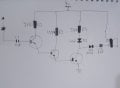
Hello, i wanted to make a emf meter for fun and to gain some learning experience , after digging around the internet I found interesting circuits but the most common circuit i found was a 3 stage darlington amplifier based design so i made it with some tweaks of my own
But the circuit had some problem of its own for example the (i) detection range decreases every time it detected emf (ii) the sensitivity of the circuit was quite low
For the (ii) problem I think connecting it's output to a inverting amplifier should fix the problem but right now I do not have a opamp to use so I am not sure
Attachments
-
 2.3 MB Views: 47
Last edited:


