Trying to improve Slayer Exciter

Thread Starter

rwfwef

Joined Sep 14, 2025
68
Hi there,

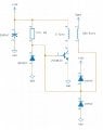
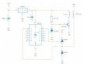
I built a slayer exciter circuit and it worked (circuit diagram in attachments). However, I wish to improve the design. One design flaw is that if I want to use a transistor that can handle more voltage, current, and power, the base needs more current to drive it. I saw a schematic online (circuit diagram) which is much more advanced. In my case I'm not looking to make a circuit like that, but something a bit more simple.

I'll put an example in attachments of what I tried to do but didn't work. Is there a way to make that circuit work?

The goal is to be able to drive this at a higher input voltage to increase output.

Also in the schematic that worked, I ended up remove the 2, 1N914 diodes so bottom of coil goes straight to base of transistor.
 

Attachments

Last edited:

Danko

Joined Nov 22, 2017
2,136
The goal is to be able to drive this at a higher input voltage to increase output.
Pay attention to $1.11 Tesla coil module
which works from 9 V or 12 V power supply:
1761995407619.png1762011175612.png
ADDED:
I want to be able to drive this at over 30V but I need to change the circuit up a bit in order to be able to drive I higher voltage, current, power transistor.
BD243C is 100 V, 6 A, 65 W transistor, drive it at over 30 V if you want.
Current from L2 to base Q1 is more than enough to control Q1, only place Q1 on big heatsink.

ADDED MORE:
PS voltage = 30 V;
HV voltage = 45 kV peak;
HV frequency = 1.8 MHz;
Power, dissipated by Q1 = 1.1 W.
1762036367331.png
 

Attachments

Last edited:

Thread Starter

rwfwef

Joined Sep 14, 2025
68
Pay attention to $1.11 Tesla coil module
which works from 9 V or 12 V power supply:
View attachment 358063View attachment 358076
Not sure what you want me to pay attention to? Anyway mine can take a 19V input but it can only run so long before the transistor overheats. I want to be able to drive this at over 30V but I need to change the circuit up a bit in order to be able to drive I higher voltage, current, power transistor. One idea was to amplify the signal coming from the L2 coil using 74HC14.

In terms of circuit design, the one I posted looks very similar to that. Again in case you missed it, I didn’t remove the 2, 1N914 diodes.
 

schmitt trigger

Joined Jul 12, 2010
2,027
The transistor is not voltage driven but current driven.
Use the original circuit, the one that it is working, and use a darlington transistor configuration. Everything else remains the same, including the blue LED instead of the UF4007, and the bottom 1N4148 should be removed because it will shunt away any base drive current.
 

MisterBill2

Joined Jan 23, 2018
27,159
Certainly the alternative circuit shown in post #1 is very elaborate indeed.
There are a lot of other TESLA coil circuits around that are quite good and much less complex. I have even seen a few of them on this website,
My evaluation is that all of the better SIMPLE driver circuits that work very well use a separate coil for the feedback to the oscillator transistors. The benefit is much more reliable operation, and much less dependence on capacitor coupling to provide adequate feedback. The actual circuit is similar to many of the self excited power inverters from years past. The main difference being in the construction of the coils, being air core rather that iron core.
 

Thread Starter

rwfwef

Joined Sep 14, 2025
68
Certainly the alternative circuit shown in post #1 is very elaborate indeed.
There are a lot of other TESLA coil circuits around that are quite good and much less complex. I have even seen a few of them on this website,
My evaluation is that all of the better SIMPLE driver circuits that work very well use a separate coil for the feedback to the oscillator transistors. The benefit is much more reliable operation, and much less dependence on capacitor coupling to provide adequate feedback. The actual circuit is similar to many of the self excited power inverters from years past. The main difference being in the construction of the coils, being air core rather that iron core.
So let’s say I put a in a feedback coil and I make it the same as my L1 coil (3 turns, same radius, and height), would the voltage on that feedback coil be near the same voltage across the L1 coil?
 

MisterBill2

Joined Jan 23, 2018
27,159
Under no load conditions t e voltage ratio is very close to the turns ratio. But you also need to understand the oscillator circuit, and what voltages exist when it is functioning. So at this point I am going to suggest reading some of the literature that discusses oscillators. There are authors who are much better at explaining the theory than I am.
Probably a few folks who frequent this forum can explain the details of a feedback-coil oscillator.
 
Top