What type of connectors are being used and how do they connect to the batteries?
What makes you think you'll be able to get 5A from each of the batteries? The battery with the highest voltage will provide more current (and will tend to charge the lower voltage batteries). Eventually the battery voltages will equalize, but the stronger battery will still provide more current.
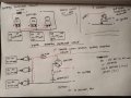
What is the purpose of the zener diode? As drawn, it's being used like a regular diode. If you use it as a zener, the MOSFET will barely conduct.
What will be powered by this circuit? What is its voltage tolerance? What is the battery chemistry involved?
If you drew a proper schematic, you wouldn't need to label the terminals on the MOSFET. Even with just one of each type of component, I'd still use component designators (Q1, R1, D1).
Just to add a little more on one of the issues above: A MOSFET passes virtually no gate current except a tiny burst when the gate charges or discharges. Think of it as a capacitor - no DC passes. So the zener will not be able to control the voltage there as drawn.
Is under-voltage the only kind of protection you want? Holding the gate at 12V while source-drain voltage is higher than 12V would limit current flowing. The MOSFET would conduct once the battery voltage (same as source-drain) falls to 12V and below.
What will be most useful is if the TS describes how the circuit is supposed to be working, and what conditions it is supposed to protect the batteries from. Then the different brilliant folks who help us will be able to ask questions, and we will all learn.
 Facebook
 Google
 GitHub
 Linkedin
 263.2 KB Views: 22


