hi,
You would get only 0.65V because you do not have a series resistor, you are shorting pin 3 to 0v via the transistor BE junction [ Not recommended]
E
With an output current of only 2.2mA then the TLC555 does not need an output resistor to "limit" the current because it is already limiting the current. The transistor will saturate only if you limit its output current to 2.2mA x 10= 22mA but the very low value of the collector resistor is causing the collector voltage to be far from saturation. You do not have enough base current, that is why I said do use two transistors to increase the current.
The output current of a TLC555 can go low with almost 10 times the current of it going high which is also a bonus if you use two transistors. Its maximum allowed output low current is 150mA so use a series resistor to limit its output current to about 5mA. Then the base of the PNP transistor gets 5mA and its output will be saturated at 50mA. Limit the current to 20mA for the base of the NPN transistor so its output can saturate at 200mA into the IR LED.
I followed some idea just to establish is it transistor in saturation mode.If a have 2.2 mA in base region i must multiply that with a factor of 10.This much curent(22 mA) should run from colector to emiter but only if: Vce=0(if we look at the graph of Vce and Ic for saturation of the transistor we must equal Vce with 0. Only then Ic would be maximum(22mA) and we can said that it is in saturation mode.Then i tried to calculate Vce to be 0.From 3V suply i must loose all 3V on collector region:So I want my IR led to have a voltage of 1.2 V(3-1.2 =1.8 V),then i calculated 0.3 V drop on the colector emiter(1.8-0.3=1.5V).1.5 V that left i must loose on a resistor,but with a curent of 22mA so it would be 1.5/22mA=68 ohms...i dont know probably i am wrong but still its interesting to learn something new.
Won't the range be very short if the current in the IR LED is only 22mA? Won't the range be much longer if the LED gets 220mA?
Will the circuit still be useful when the battery voltage has dropped to only 2V?
If the IR LED will survive 220mA then your circuit needs two transistors.
Won't the range be very short if the current in the IR LED is only 22mA? Won't the range be much longer if the LED gets 220mA?
Will the circuit still be useful when the battery voltage has dropped to only 2V?
If the IR LED will survive 220mA then your circuit needs two transistors.
Yes,i know.Everything you said its true.I tried just to observe if anything will hapen.But since it didnt i was wrong in some point.Guesing that is because there is a short circuit when there is no base resistor and when it ocurs there is 0V drop(in this case 0.65 V although i dont know where it come from??) Tomorrow i will start to use 2 transistor so i hope good things will emerge
A TLC555 has a low output-high current. Its output current is higher when it has a higher supply voltage that you do not have. Its output current is also higher when it drives a dead short and the base-emitter of an NPN transistor (0.7V) is almost a dead short.
The output low current of the TLC555 is almost 10 times the output high current so you can use a series resistor from its output to the base of a PNP transistor. If you want 220mA in the 1.2V IR LED when the battery is 3V then the resistor feeding the LED should be (3V - 1.2V - 0.5V)/220mA= 5.9 ohms. The 0.5V is the Vce saturation voltage of a 600mA 2N4401 NPN transistor with a 220mA collector current and a 22mA base current.
The NPN transistor base will be driven to 0.7V and be driven through a current-limiting resistor from the 2.7v saturated collector of a 2N3906 PNP transistor. The base resistor is (3V - 0.3V - 0.7V)/22mA= 91 ohms.
The 2.3V base of the PNP needs 2.2mA through a current limiting resistor from the output low of the TLC555 which will be 0.24V. Then the series resistor is (2.3V - 0.24V)/2.2mA= 936 ohms (use 910 or 1k).
I checked datasheet of my TSUS 5402 IR led and it holds 150 mA forward curent and peak forward curent (Ifm) of 300 mA(tp/T=0.5,tp=100 micro s).Does this peak forward curent means that with 50% d.c. and duration of high puls of 100 micro s my diode can reach max 300 mA ???
What is surge forward curent of 2.5 A??
Should i treat IR led as a linear or a non linear element since there is a diference between these constatations???
yes
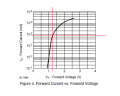
For the first graph i want to know if this meaning is true:When a forward voltage is 1.25 V the curent is aprox. 100 mA,or i need to include calculations for non linear element(direction of slope...)??
For the second graph i am confused...tp/T means a duty c.??? so if my d.c. is 65% that should mean that is tp/T=0.65??? and my tp=0.65*0.00003333=0.000021 s ??? how much is max.curent then??
yes
For the first graph i want to know if this meaning is true:When a forward voltage is 1.25 V the curent is aprox. 100 mA,or i need to include calculations for non linear element(direction of slope...)??
For the second graph i am confused...tp/T means a duty c.??? so if my d.c. is 65% that should mean that is tp/T=0.65??? and my tp=0.65*0.00003333=0.000021 s ??? how much is max.curent then??
You probably don't need more than 100 mA, probably not even that. The problem is that you not, so far, supplied anything close to that.
Since the 555 chip you are using can source 10 mA, a single PNP transistor should be able to get you around 100 mA when saturated. I would try that, verify that you are getting the expected current, and then see how it performs.
Note that the duty cycle will be reversed if you do that, but the duty cycle is not critical in making this work. I would just try to get it close to 50%.
hi.
It must not be On longer than 0.2mS
You are thinking this design back to front.
You have to decide the maximum current thru the LED that gives the light intensity required and then determine the permissible On period of the LED at that current.
The longer the On period the shorter the battery life.
What is the maximum current you require thru the LED that gives the you the required design intensity ?.................................?
Bearing in mind the life expectancy of the batter pack.
Without seeing a clear design specification for your project, it not possible to give you helpful answers.
E
Since the TLC555 is being used and its datasheet does not have a graph showing output current with different supply voltages, I use the graphs of the identical ICM7555. It shows a typical output low current with a 3V supply at 1.5V of about 8mA. Its minimum output is probably only 4mA. Then using one PNP output transistor you can guarantee an output into the IR LED of 40mA when the battery is brand new.
Hello guys!!!
Small steps but i am getting there
I menage to get a distance of 3.5 m just with PNP transistor.IR led curent is about 118 mA.
My goal is another 2 m and that's it.When i am done i will post a schematic...but still i have got so maaannnyyy questions...
If the range is 3.5m when the battery is brand new then the range might be 1m or less when the battery has run down a little.
You did not say what is the value of the series base current-limiting resistor for the PNP, and what is the battery voltage when it is working.
 Facebook
 Google
 GitHub
 Linkedin
")