IR circuit

Audioguru again

Joined Oct 21, 2019
6,826
Sorry, Eric. A simulation is not real.
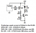
The simulation guesses that the battery is perfect with a very low impedance so that its voltage does not drop with each current pulse like what happens with a real battery. Therefore a supply bypass capacitor should be added to charge and supply current during each current pulse.
The simulation also guesses that the spec's for the IC and transistor are typical but not minimum like real parts could be.

I wonder why the resistor values for the second TLC555 are so low which uses a lot of un-needed current. The datasheet shows a timing graph with resistor values up to 10M ohms.
 

ericgibbs

Joined Jan 29, 2010
21,442
Sorry, Eric. A simulation is not real.
Gosh agu I didn't know that.!;)

Its not a final circuit design, it is a draft circuit that we can refer to and discuss.

It was created in an effort to show all the participants on this Thread and in particular to get the TS to firm up what he expects from the project. [now Post #102]

Eric

Update:
Added the LTS asc file, feel free to modify.
 

Attachments

Audioguru again

Joined Oct 21, 2019
6,826
I suggested using two transistors so that there is enough LED current even if the parts have minimum spec's and another person also suggested two transistor except the second transistor was an emitter follower so it did not invert.
Take your pick.
 

ericgibbs

Joined Jan 29, 2010
21,442
hi agu,
Have you run that sim I posted.
The TS said that he intended using a TSOP receiver, nominal 40kHz, but also said he is running the LED emitter at 30kHz.???

I think its about time he posted a clear specification for his project.
E

BTW:
I configured the LTS Lexeon LED at an approximation to the TS's LED
.model MyLED1 D(Is=2.27n Rs=0.25 N=1.65 Cjo=42p Iave=350m mfg=Lumileds type=LED)
 
Last edited:

Thread Starter

optus

Joined Oct 25, 2019
92
Hello guys
I just want to clear some things.As i said before:I dont have some special ideas of using this project.The thread was started so i can learn more about TLC itself and electronic at all.I know basic things about electronic but i want to know more.In the future i might use this project to light a bulb or drive some motor...i am not sure,but for now it is irelevant.To make things work properly i must know how to overcome various problems and that's why i ask so much guestions.First i must know how things behave so i can build something of it...If it's easiest for you let's say that i want to build a switch that would run on 30 kHZ and would light up a led on distance of 6 m via TSOP 1730 because that is what i am doing all this time...
 
Last edited:

djsfantasi

Joined Apr 11, 2010
9,237
...If it's easiest for you let's say that i want to build a switch that would run on 30 kHZ and would light up a led on distance of 6 m via TSOP 1730 because that is what i am doing all this time...
Hello... I think several people here are trying to explain to you that you can’t succeed with the design as described.

Your switch controls a 30kHz signal.

The TSOP 1730 only receives signals at 38kHz.

I hope you can see the issue. 30 does not equal 38. It’s like trying to start your car with your house key. It just ain’t gonna happen.
 

Bernard

Joined Aug 7, 2008
5,784
To use the Rx output to control a motor, LED, ?, you may want to integrate the signal as illustrated in this 5 yr. old incomplete drawing. This one might be the one that Rx could not hide from the Tx or straight line about 12 m.IR Tx 00000.png
 
Last edited:

Thread Starter

optus

Joined Oct 25, 2019
92
Hello... I think several people here are trying to explain to you that you can’t succeed with the design as described.

Your switch controls a 30kHz signal.

The TSOP 1730 only receives signals at 38kHz.

I hope you can see the issue. 30 does not equal 38. It’s like trying to start your car with your house key. It just ain’t gonna happen.
I must disagree!
TSOP 1730 is designed for 30 kHZ and that we can se by two last number of his name
 

djsfantasi

Joined Apr 11, 2010
9,237
I must disagree!
TSOP 1730 is designed for 30 kHZ and that we can se by two last number of his name
i re-read datasheet. My mistake.

The chart at the beginning of the DS does state that the 1730 has a 30kHz carrier.

I was looking later in the DS where it states that the carrier is 38kHz without qualifying it by specific chip #s.
 

Thread Starter

optus

Joined Oct 25, 2019
92
To use the Rx output to control a motor, LED, ?, you may want to integrate the signal as illustrated in this 5 yr. old incomplete drawing. This one might be the one that Rx could not hide from the Tx or straight line about 12 m.View attachment 190409
Nice scetch...thank you.
Because of the diode i can see that it was build for d.c. less than 50 %.i would look into more when i can.
 

peterdeco

Joined Oct 8, 2019
484
Optus, you should look into using a microcontroller for IR transmitting and receiving to reduce parts count. All I used was a PIC 12F675, a mosfet, 2 resistors, a cap and the IR LED. That's it. I programmed 5 of these transmitters with different codes at 32KHZ so they wouldn't interfere with each other. Also, like I previously mentioned, stick your IR LED in a rubber grommet. It increased the range of my transmitters from a few feet to across a large room. Why? I don't know.
 

Thread Starter

optus

Joined Oct 25, 2019
92
Optus, you should look into using a microcontroller for IR transmitting and receiving to reduce parts count. All I used was a PIC 12F675, a mosfet, 2 resistors, a cap and the IR LED. That's it. I programmed 5 of these transmitters with different codes at 32KHZ so they wouldn't interfere with each other. Also, like I previously mentioned, stick your IR LED in a rubber grommet. It increased the range of my transmitters from a few feet to across a large room. Why? I don't know.
Thank you
Did you mean something like arduino? Unfortunately i am not so good at programing...beside that i do not know exactly how these microcontrolers work.Do they need some code to function properly or what?
 

Thread Starter

optus

Joined Oct 25, 2019
92
Yes they require code. Years ago I started learning with Chip Factory from Revolution Education. The I went to PicBasic Pro from Micro Engineering Labs. There is also a great forum for PicBasic with fine people eager to help each other. Here's a link to the forum. IR projects have been discussed many times in the past. http://www.picbasic.co.uk/forum/forumdisplay.php?f=4
Thank you!
Maybe i will try some day.
 

Thread Starter

optus

Joined Oct 25, 2019
92
So i build up a transmiter circuit consisting of 2 x TLC 555CP as an oscilator circuit for frequency of 30 kHZ,and a suply of 2x1.5 V bateries.To amplify curent i conected PNP(BC 328)to the pin 3 of first oscilator.Base resistor is 1.8 ohms and colector resistor is 3.6 ohms.I ve got curent of 7 mA runing through base emiter region and about 70 mA runing through an IR led (colector region).
In reciever circuit there is a TSOP 1730 conected to a green LED and a resistor,just to establish distance and wheter is circuit working or not.
The range is about 4 m and that is OK.
When i conect second transistor(NPN 1740's base to colector of PNP) i am getting only about 30 mA through IR led.
My calculations are as follows:
Since forward curent for my IR led is 150 mA i want about 140 mA through IR led and colector of NPN transistor.From the datasheet of ICM7555 for curent of about 1.4mA required voltage is about 0.15 V so 3V-0.15-0.7=2.15/0.0014 A = 1535 ohms in base.In colector which is conected to the base of NPN now is flowing 14mA.
Base resistor of NPN is 3-0.7(saturation of Vce when curent is 14 ma)-0.82(Vbe on for curent of 140 mA)/0.14 A=10.6 ohms.
Colector region is 3-1.2-0.17 V/0.14 A=11.65 ohm.
But it doesnt work.Where i am wrong?
Oscilator circuit is supose to work as on/off switch for TSOP 1730 which is going to light up/shut off a green led for now...
 

BobTPH

Joined Jun 5, 2013
11,515
Those resistors are much too small to do anything about current limiting, the current is being limited instead by what the chip can source or sink, or possibly even by the battery. This is not a good design.

Do yourself a favor, use another cell to get 4.5V and use a MOSFET to switch. Then you will have a robust design that will continue to work even when the battery is run down.

Bob
 

Thread Starter

optus

Joined Oct 25, 2019
92
Those resistors are much too small to do anything about current limiting, the current is being limited instead by what the chip can source or sink, or possibly even by the battery. This is not a good design.

Do yourself a favor, use another cell to get 4.5V and use a MOSFET to switch. Then you will have a robust design that will continue to work even when the battery is run down.

Bob
Thank you.
I was wondering how do remote controls for TV and car works??? They use 3 V suply
 

Audioguru again

Joined Oct 21, 2019
6,826
Optus, you did not show a schematic for your calculations so I do not know where you went wrong. I calculated for 210mA when the battery is new, use 9.1 ohms for R4 to get 143mA:
 

Attachments

Thread Starter

optus

Joined Oct 25, 2019
92
Optus, you did not show a schematic for your calculations so I do not know where you went wrong. I calculated for 210mA when the battery is new, use 9.1 ohms for R4 to get 143mA:
Thank you...i dont have any program for drawing schematic.Only way is to draw with hand...i will try to hand draw then i will post.
Once more,thank you!
 

Audioguru again

Joined Oct 21, 2019
6,826
I also do not have a program to do schematics. Instead I copy parts from other schematics and datasheets then paste them into Microsoft Paint program.
Did you open and understand my attachment?
 
Top