Oh it's no biggie. these things work on trial and error for me when it comes to mosfets.
So I won't blow up any thing, it simply wouldn't work that efficiently, am I right?
I don't know how fast or often your supply is trying to switch those MOSFETs. I can tell you that those new MOSFETS will switch at about 1/3 the speed they were switching before, which means lots more time for them to get toasty.
As you already know, the higher their temp, the higher their Rds(on) gets.
If you really want to improve the thing, use MOSFETs that have the same or lower Rds(on), about the same Vdss rating, and a lower gate charge. The lower you can get the gate charge, the faster they will switch, and the lower the heat dissipation during the switching.
The longer the MOSFETs stay in the linear region (partially conducting; between ON and OFF) the longer they dissipate heat.
The faster the inverter controller is operating, the more current it's going to take to switch those MOSFETs on and off. If it's trying to operate above, say, 100kHz, the MOSFETs are going to spend most of their time in the linear region generating heat.
Yeah of course it will generate heat. power switches do that.
I am wondering in my case, why replacing them with ones I have will effect the heat developed
it will slow down the operation. takes more time to charge. means the FET spends more time in the active region thus more heat.
hey...I'm a genius.
Now don't you wish every one understands things that way ..when u try to explain them stuff
OK, previously you had five MOSFETs, each had a gate charge of 72nC, so that's 360nC. If your controller is running at 100kHz, it will dissipate 360mW.
You've increased the total gate charge to 240, for a grand total of 1,200nC's, and a power dissipation of 1.2 Watts.
I hope your controller has a good heat sink on it.
U see the thing is I can read data.
But I am not so familiar with FET's.
I can get a replacement for a transistor any day, but when it comes to FET's, I tend to blow them up pretty often, SO know I am trying to understand why the heck.
I compare data the same way as transistors but it doesn't help. Cause most of the time..BANG. ...and I had to find the exact part no. and the crap sold here does not last a minute.
I remember repairing one inverter. It had a shorted MOSFET. So I took it out and tested the inverter, it worked, cause it had plenty of them in it. But I know if one is less, the others have to take the burden. So I bought one from here, cause I did not have tht no. and guess what the bloody thing shorted when it was loaded.
So only way was to remove it, and it worked pretty well. Best part is it had one more FET removed from previous attempt. .
So now actually two is missing from it.
This tells me I cannot rely on the cheap crap components I can get.
I had to find a replacement. Now the components I have a good, cause most of them are pulled from working items. All are in my vault.
I am trying to figure out this MOSFET replacement thingy from Sgt, as I have seen big daddy is pretty good at handling MOSFET's, so I had to annoy him or bug him to get as much info as I can.
This is a customer's Inverter, and I already had said I will give it within a few hours.
Sorry that I had to leave. I'm taking some refresher courses in the evenings during the week, so I'm just not available during that time. It takes me 45 minutes to drive there one way, and I'm there for 3 hours.
The four basic things you need to look at when comparing MOSFETs is:
1) The threshold voltage. If your original MOSFET is a logic-level MOSFET, it will have specifications for Rds(on), etc. given with Vgs<=5v as well as when Vgs=10. You can often replace a standard MOSFET with a logic-level MOSFET, but not the other way around.
2) The Vdss rating. Very generally, the higher the Vdss rating is, the more of a penalty you will pay in Rds(on) and total gate charge. You need to establish the minimum Vdss that is required for the circuit that you are working on.
3) The Rds(on) at your working Vgs. Lower is better, of course. However, to get Rds(on) lower, you usually have to look at a higher gate charge. Rds(on) is directly related to the Id rating.
4) Qg, or the total gate charge. You can buy what seems to be the most wonderful MOSFET in the world; Vdss of a zillion volts, Rds(on) of 0.001 milliOhms, but if that gate charge is 99 Coulombs, it'll take a week to charge the gate using 10 car batteries in parallel. In the meantime, the MOSFET will be glowing red-hot from all of the power it's dissipating while in the linear region.
There have been lots of improvements in MOSFETs over the last decade or so, and you have a LOT more choices than were available in years past. That makes choosing an appropriate replacement MOSFET seem more bewildering, simply because there are so doggone many on the market now.
However, you have powerful parametric search engines available on many manufacturer and vendor's sites. Fairchild Semiconductors' search engine is pretty good.
Digikey.com is also pretty good.
So is Mouser.com
You might start a parameter search by specifying the type (N-ch or P-ch), a range of Vdss (from somewhat less than the original part's specifications to perhaps 3x as much), and then from the results you get, start looking at Rds(on) vs gate charge.
If the circuit you are working on has a capable gate driver and is running at low to moderate speed, then you might opt for the lower Rds(on) specification.
In your current situation, you have a gate driver capable of sourcing/sinking 500mA, but it's driving five MOSFET gates, and it is likely switching at a rather high rate of speed. In this case, you should opt for a gate charge that is lower than the originally specified MOSFETs. A low Rds(on) means nothing if the MOSFET(s) are spending much of their time in the linear region.
The IRFZ46 MOSFETs have a far lower Vdss than the original IRF540, at 55v vs 100v. I don't know if that will be enough for your application. The gate charge is slightly lower, but that won't help if the first time they're switched they blow up due to Vdss being exceeded.
Knowing the switching frequency and actual drain voltage peaks would help quite a bit in determining a replacement MOSFET.
The failures you are finding may be attributable to heat or unstable power. I don't know how good your power grid is there. It's very unstable in many parts of the world; it's not a problem where I live, so I don't think about it much.
Heat is definitely a problem. From the images you've posted, it looks like you live in a tropical paradise. However, if temps go up, commercial grade electronics have a hard time coping with it. Corrosion due to salt air is also a problem.
You may find that retrofitting parts with more/better fans to circulate air through the enclosure will help a good bit. Remember, as MOSFETs get warm/hot, their resistance increases. This helps with load sharing, but if ALL of the MOSFETs are hot, you are looking at a melt-down in the making.
No need for apologies Sgt. I know the time taken, that's why I haven't done anything yet, just waiting for ur reply.
Any input as much as a yell is helpful to me and I take that pretty seriously.
I may be good at what I do but I know when I meet certain people who have better knowledge than me and I always respect them for the time and the things they share to help others, I know as I do the same.
Just know tht I will never expect an apologies from the older members here for anything, even though should something arise. The way I see it I am much younger than any of you here, as a matter of fact I may be the youngest genius here .
So I'll be the who always apologize. Not you guys
The four basic things you need to look at when comparing MOSFETs is:
1) The threshold voltage. If your original MOSFET is a logic-level MOSFET, it will have specifications for Rds(on), etc. given with Vgs<=5v as well as when Vgs=10. You can often replace a standard MOSFET with a logic-level MOSFET, but not the other way around.
2) The Vdss rating. Very generally, the higher the Vdss rating is, the more of a penalty you will pay in Rds(on) and total gate charge. You need to establish the minimum Vdss that is required for the circuit that you are working on.
3) The Rds(on) at your working Vgs. Lower is better, of course. However, to get Rds(on) lower, you usually have to look at a higher gate charge. Rds(on) is directly related to the Id rating.
4) Qg, or the total gate charge. You can buy what seems to be the most wonderful MOSFET in the world; Vdss of a zillion volts, Rds(on) of 0.001 milliOhms, but if that gate charge is 99 Coulombs, it'll take a week to charge the gate using 10 car batteries in parallel. In the meantime, the MOSFET will be glowing red-hot from all of the power it's dissipating while in the linear region.
Exactly what I needed to know..see what I meant. Now I know I cannot find this googling
However, you have powerful parametric search engines available on many manufacturer and vendor's sites. Fairchild Semiconductors' search engine is pretty good.
Digikey.com is also pretty good.
So is Mouser.com
If the data is on the net, then I will find it, but this was not the case here
IRFP260 / 460 I have are parts that I bought from suppliers direct. I bought them for a job, when I buy something, I buy plenty just in case, so these FET's are just sitting there, cause the item I repaired never developed a fault
If the circuit you are working on has a capable gate driver and is running at low to moderate speed, then you might opt for the lower Rds(on) specification.
In your current situation, you have a gate driver capable of sourcing/sinking 500mA, but it's driving five MOSFET gates, and it is likely switching at a rather high rate of speed. In this case, you should opt for a gate charge that is lower than the originally specified MOSFETs. A low Rds(on) means nothing if the MOSFET(s) are spending much of their time in the linear region.
I haven't gone through voltage measurement of this inverter as I have not yet been able to finalize the FET's, so I cannot say anything yet
The IRFZ46 MOSFETs have a far lower Vdss than the original IRF540, at 55v vs 100v. I don't know if that will be enough for your application. The gate charge is slightly lower, but that won't help if the first time they're switched they blow up due to Vdss being exceeded.
Ya....tht Vdss was something I thought of too. But I think it will work cause these z46 are working pulls from a 1.2KVA APC UPS, which uses 24VDC. So these Fets can withstand the voltage, the inverter too is 24VDC.
I have done a quick research on the inverter, it is a modified sine wave type.
The small FET's are used for the DC voltage boost and the big one are wired as H-Bridges.
So I think This might work
The failures you are finding may be attributable to heat or unstable power. I don't know how good your power grid is there. It's very unstable in many parts of the world; it's not a problem where I live, so I don't think about it much.
Our grid is quite stable, this inverter is from a safari
Heat is definitely a problem. From the images you've posted, it looks like you live in a tropical paradise. However, if temps go up, commercial grade electronics have a hard time coping with it. Corrosion due to salt air is also a problem.
Yes ....you are right here. The temp is quite high, that is why the failure rate is high, but I cannot help it, as none of the dingbats here will believe it if I explain it, they just don't want to spend money on qualified tech, Instead they would waste it on some double crossing hooligun. Story of my life
You may find that retrofitting parts with more/better fans to circulate air through the enclosure will help a good bit. Remember, as MOSFETs get warm/hot, their resistance increases. This helps with load sharing, but if ALL of the MOSFETs are hot, you are looking at a melt-down in the making.
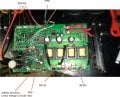
See the PIC.
As you can see I have replaced the faulty 540's with Z46.
But before that I powered up and the thing started to smoke, so further checking showed a faulty PWM, replaced that and I got the gate drives for the converter which are always around at 5V. for the Z46 and 540
The faulty 540's have shorted GS, which means the PWM could have caused these FET's to blow. I replaced the whole bank with Z46 and the other side is as it is. I can get 250VDC now.
Before even measuring I got the kick of it when I touch the Tabs of the rectifies together with regulator GND Tab. I was checking to see how hot the TO-220 were getting. Answer I got was quite tantalizing.
As I said I can measure 250VDC between the IRFP450 H-Bridge.
The Z46's gets a little warm compared to the 540's in free air. I ran without load as the sink was not mounted.
The H-bridge is driven by a 556 the drivers are 4 mid power MJE13003 and it's counter part pairs.
Gate to Source voltage are at 5.7V and 6.1V ...2 450 have 5.7V and other 2 has 6.1V alternate.
I have 2 q.
1) is that the extra heat dissipation in the z46 are due to lower Vdss or due to gate charge or not?
2) is will IRFP460 Will work as H-Bridge?

 Facebook
 Google
 GitHub
 Linkedin