
 Facebook
 Google
 GitHub
 Linkedin

Hello everyone, in my three-phase inverter operating at 48V, with a DC bus current of [0..4]A and a maximum phase current of 5–6Arms I thought it would be enough to control the overcurrent using only the phase current feedback.
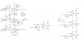
In some online schematics (from UM1996 X-NUCLEO-IHM08M1), I have noticed that they separate the current feedback path (which goes to the microcontroller, used in FOC control, etc.) from that of the overcurrent protection by using a comparator on one of the three phases:
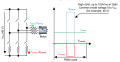
However, I’ve noticed a difference compared to my schematic: I measure the direct in-shunt current directly on the motor phases, whilst ST measures it on the source leg of the MOSFETs:
1) Can I integrate this comparator solution with my inline shunt current sensing?
2) If so, which of these two is correct? And why?
I’ve tried to sketch a rough draft:
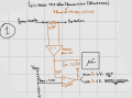
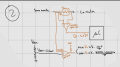
I think the first option is better because generating a Vref of just 42 mV (like the solution 2) is so sensitive that I would risk false OCP readings.
3) Provided it is possible to use this comparator circuit ... I also wonder whether it makes sense to do so for just one of the three phases or for all three; I believe ST only does it on one, requiring you to desolder the resistors from the other two comparators...
I’d also like to take this opportunity to kindly ask for your advice on any RC filters, NPN transistors to invert the logic after the comparator, etc. any advice is welcome!
----------------------EDIT---------------------
I calculated the INA output as follows: Vo,max = Rsh*Iphase,pk*Gain+ Vref)
In some online schematics (from UM1996 X-NUCLEO-IHM08M1), I have noticed that they separate the current feedback path (which goes to the microcontroller, used in FOC control, etc.) from that of the overcurrent protection by using a comparator on one of the three phases:
However, I’ve noticed a difference compared to my schematic: I measure the direct in-shunt current directly on the motor phases, whilst ST measures it on the source leg of the MOSFETs:
1) Can I integrate this comparator solution with my inline shunt current sensing?
2) If so, which of these two is correct? And why?
I’ve tried to sketch a rough draft:
I think the first option is better because generating a Vref of just 42 mV (like the solution 2) is so sensitive that I would risk false OCP readings.
3) Provided it is possible to use this comparator circuit ... I also wonder whether it makes sense to do so for just one of the three phases or for all three; I believe ST only does it on one, requiring you to desolder the resistors from the other two comparators...
I’d also like to take this opportunity to kindly ask for your advice on any RC filters, NPN transistors to invert the logic after the comparator, etc. any advice is welcome!
----------------------EDIT---------------------
I calculated the INA output as follows: Vo,max = Rsh*Iphase,pk*Gain+ Vref)






