Overcurrent protection using comparator in inverter

Thread Starter

andrew74

Joined Jul 25, 2022
273
Hello everyone, in my three-phase inverter operating at 48V, with a DC bus current of [0..4]A and a maximum phase current of 5–6Arms I thought it would be enough to control the overcurrent using only the phase current feedback.

In some online schematics (from UM1996 X-NUCLEO-IHM08M1), I have noticed that they separate the current feedback path (which goes to the microcontroller, used in FOC control, etc.) from that of the overcurrent protection by using a comparator on one of the three phases:
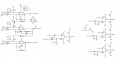
1790880839327.png

However, I’ve noticed a difference compared to my schematic: I measure the direct in-shunt current directly on the motor phases, whilst ST measures it on the source leg of the MOSFETs:
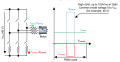
1790881386138.png

1) Can I integrate this comparator solution with my inline shunt current sensing?


2) If so, which of these two is correct? And why?
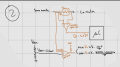
I’ve tried to sketch a rough draft:
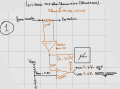
1790880961036.png

1790880992283.png

I think the first option is better because generating a Vref of just 42 mV (like the solution 2) is so sensitive that I would risk false OCP readings.

3) Provided it is possible to use this comparator circuit ... I also wonder whether it makes sense to do so for just one of the three phases or for all three; I believe ST only does it on one, requiring you to desolder the resistors from the other two comparators...

I’d also like to take this opportunity to kindly ask for your advice on any RC filters, NPN transistors to invert the logic after the comparator, etc. any advice is welcome!

----------------------EDIT---------------------
I calculated the INA output as follows: Vo,max = Rsh*Iphase,pk*Gain+ Vref)
 

panic mode

Joined Oct 10, 2011
5,277
hmmmm....

did you have basic AC/DC circuit courses? do you understand Kirchhoff's laws?

sum of all currents entering and leaving node is always zero. your motor can be seen as one such node where three wires are tied together (somehow, inside motor, maybe Wye, maybe Delta, but there is continuity inside motor from phase to phase...).

if current of phase1 is 4A (positive means entering motor), then combined current in phase2 and phase 3 must be -4A (leaving motor).
maybe phase2 is -2A and phase3 is -2A
maybe phase2 is 1A and phase3 is -5A...
this is what allows measuring currents using shunts the way ST shows, instead of inline with motor wires like INA240 datasheet shows.

btw. if you know two of the currents, you can calculate the 3rd one.
did not look at ST docs but if i was measuring current using single shunt, i would NOT measure single phase current. i would make sure to place shunt so all motor currents flow through it (either single shunt at positive rail or at negative rail).
think about it. what happens if motor or mosfets fail and you have a short circuit on one phase but that is not the phase you are monitoring? measuring all three is a good thing, a sanity check plus you get to see if there is a problem - leakage current (cable damage for example etc.)

about comparators...
why do you think that LMV331 can be used in second circuit? did you read the datasheet? it clearly says that this is a 5V part but your circuit #2, one of the comparator inputs is connected to Vphase! how do you ensure that Vphase never exceeds 5V?
 

Thread Starter

andrew74

Joined Jul 25, 2022
273
hmmmm....

did you have basic AC/DC circuit courses? do you understand Kirchhoff's laws?

sum of all currents entering and leaving node is always zero. your motor can be seen as one such node where three wires are tied together (somehow, inside motor, maybe Wye, maybe Delta, but there is continuity inside motor from phase to phase...).

if current of phase1 is 4A (positive means entering motor), then combined current in phase2 and phase 3 must be -4A (leaving motor).
maybe phase2 is -2A and phase3 is -2A
maybe phase2 is 1A and phase3 is -5A...
this is what allows measuring currents using shunts the way ST shows, instead of inline with motor wires like INA240 datasheet shows.

btw. if you know two of the currents, you can calculate the 3rd one.
did not look at ST docs but if i was measuring current using single shunt, i would NOT measure single phase current. i would make sure to place shunt so all motor currents flow through it (either single shunt at positive rail or at negative rail).
think about it. what happens if motor or mosfets fail and you have a short circuit on one phase but that is not the phase you are monitoring? measuring all three is a good thing, a sanity check plus you get to see if there is a problem - leakage current (cable damage for example etc.)

about comparators...
why do you think that LMV331 can be used in second circuit? did you read the datasheet? it clearly says that this is a 5V part but your circuit #2, one of the comparator inputs is connected to Vphase! how do you ensure that Vphase never exceeds 5V?
Hi, and thank you for your reply.

You’re right – in Image 2, I connected the comparator’s positive input directly to the voltage on the motor phase (which is well over 5V...)... so I’d rule that out straight away; It was an oversight on my part

As regards reading the currents, I didn’t explain myself clearly in the main post. I carry out the in-line current sensing on all three phases… but for the sake of simplicity, I’ve only drawn one in the picture.

1) So am I right in saying that option 1 is correct and that I can follow the same procedure for the other two phases as well?

2) The comparator’s output switches when Vshunt > Vref, i.e. when there is a positive current peak on the phase. But if there were a negative peak, it wouldn’t switch, would it?
Let’s assume that the threshold at which I want to signal an open circuit (OC) is >=6Apk.
Let’s also assume that in an instant:
- Iphase1 = -6
- Iphase2 = 3
- Iphase3 = 3
I have one phase where the (negative) peak has dropped to 6Apk, but the other two (which are positive according to Kirchhoff’s laws) haven’t … so the comparators aren’t triggering
I think this is a problem (?)
(look at the second screenshot further down)


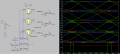
--------------------------------Simulation where the current threshold for OC fault is set to 8.48Apk--------------------------------
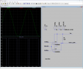
Ru, Rv and Rw are motor resistors (I know, the inductors are missing, but that doesn’t matter in this simulation) and I’ve just reduced the value of Ru to simulate a phase current that exceeds the threshold by approximately 8.48 Apk… indeed, the comparator output switches.
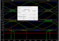
1790937162192.png

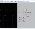
My doubt regarding question 2) is in fact confirmed here: as the current is negative (less than -8.48A), the circuit obviously does not trip:
1790937262793.png
 
Last edited:

Thread Starter

andrew74

Joined Jul 25, 2022
273
View attachment 371884

open collector output can be tied together but in this case ref points need to be swapped and you get inverted signal
View attachment 371885
Thanks again for your reply!

I found this article interesting:
https://www.ti.com/lit/an/snoaa40a/...l=https%3A%2F%2Fwww.ti.com%2Fproduct%2FINA240

The motor runs from 0 to 250rpm (therefore 0–33 Hz electrical with 8 pairs of poles) and the FOC has a frequency of 30kHz.
Do you think that it is good practice add some filters in the comparator stage?
 
Top