IL300 Optocoupler Simulation Problem

Thread Starter

Guru_Prasad_7

Joined Dec 28, 2025
10
Hi,

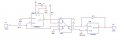
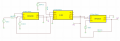
I'm trying to build a circuit using an IL300 optocoupler. My application is to read an input voltage in the range of 0V to 2V. I followed the IL300 application guide and built my circuit according to the photovoltaic configuration (as suggested in the app note).

I'm simulating the circuit in TINA, but when I run the simulation, the output is always 5V regardless of the input voltage. I'm using OPA2328 op-amps on both the input and output sides of the IL300. I downloaded the IL300 SPICE model from the manufacturer's website.

I’m not sure how to solve this problem. Could you please suggest solutions or point out where I might be making a mistake? I’ve attached my schematic and the IL300 SPICE model for reference.

Thanks & Regards
 

Attachments

ronsimpson

Joined Oct 7, 2019
4,645
Try changing iso-ground to ground.
I think iso-ground is not connected to anything.
There is no isolation because the power supplies for both op-amps are the same. You should use the same grounds.
 
Last edited:

crutschow

Joined Mar 14, 2008
38,316
It would appear that you have the output of the left op amp going to the cathode of the LED input, not the cathode as shown below from their app note.
That would generate positive feedback and likely cause the output you are seeing.

1766938155390.png
 

Thread Starter

Guru_Prasad_7

Joined Dec 28, 2025
10
It would appear that you have the output of the left op amp going to the cathode of the LED input, not the cathode as shown below from their app note.
That would generate positive feedback and likely cause the output you are seeing.

View attachment 361269
Hi there,

I'm actually following the positive unipolar photovoltaic isolation amplifier configuration which is shown in Figure-8.
 

crutschow

Joined Mar 14, 2008
38,316
Hey Hey
My sim showed a problem with the circuit design.
When using only positive op amp power (as you show), the output op amp needs to be connected to the anode, not the cathode of the opto output, so that the op amp output is non-inverting with respect to the input signal.
This is because the op amp output can't go negative without a negative supply.
(Example circuit LTspice sim below):

Note the reduced value for R1 so U3's output doesn't need to go below 0V for the peak LED current (since it can't).

(Aside -- The likely reason your circuit hung at the positive rail, is because you didn't include the ground at the opto output as the Figure 8 schematic shows, which is needed to carry the op amp input bias current.
This ground, of course, can be isolated from the input ground, but must be common with the rest of the output signal and power ground.)

Nit: You should use the standard triangular symbol for the op amps instead of the rectangular box on your schematics, as that makes it much easier to understand the circuit operation, and your schematics won't look like they were made by a newbie.


1766988539967.png
 

Thread Starter

Guru_Prasad_7

Joined Dec 28, 2025
10
Hey Hey
My sim showed a problem with the circuit design.
When using only positive op amp power (as you show), the output op amp needs to be connected to the anode, not the cathode of the opto output, so that the op amp output is non-inverting with respect to the input signal.
This is because the op amp output can't go negative without a negative supply.
(Example circuit LTspice sim below):

Note the reduced value for R1 so U3's output doesn't need to go below 0V for the peak LED current (since it can't).

(Aside -- The likely reason your circuit hung at the positive rail, is because you didn't include the ground at the opto output as the Figure 8 schematic shows, which is needed to carry the op amp input bias current.
This ground, of course, can be isolated from the input ground, but must be common with the rest of the output signal and power ground.)

Nit: You should use the standard triangular symbol for the op amps instead of the rectangular box on your schematics, as that makes it much easier to understand the circuit operation, and your schematics won't look like they were made by a newbie.


View attachment 361283
Hey,

Thanks for pointing out. When I'm trying to simulate in my LTspice, I'm not getting proper output meaning, the output is saturating to 900mV only even though my input voltage is zero. I'm suspecting there might be some issue with the spice model. Can you kindly share the sim file or just the spice netlist code so that I can once again run the simulation?

Thanks for the support..
 

ericgibbs

Joined Jan 29, 2010
21,390
Hi GP7,
That +900mV offset at the Voutput is due to the fact the OPA cannot go down to Zero Volts when using a single power supply voltage.
E
 

Thread Starter

Guru_Prasad_7

Joined Dec 28, 2025
10
Hi GP7,
That +900mV offset at the Voutput is due to the fact the OPA cannot go down to Zero Volts when using a single power supply voltage.
E
Hi,

Yes I agree but, when I'm giving input voltage as 2V, I have to get same voltage on the output side as well. Since my application involves only positive output values, I gave +5V for VCC of opamp and GND to VEE of opamp. Is there anything else that is missing?
 

ericgibbs

Joined Jan 29, 2010
21,390
hi GP7,
To show the Negative output swing of the OPA, I have used a -5V supply.
Note the way you have the circuit configured, Inverts the signal sense.
E
EG 1936.png
 

schmitt trigger

Joined Jul 12, 2010
2,027
I have actually physically built and produced a circuit utilizing the Broadcom HCNR201, which is an identical device, for the exact same application, high performance isolated voltage sensing.

I used the circuit in figure 15B, which works extremely well but requires two optocouplers.

You could try the circuit in figure 15A, which requires a single optocoupler, but the isolated current sources need to be tightly matched and to track across the temperature range. Easier said than done.

But if you are only simulating it, you could give it a try.
 

Attachments

eetech00

Joined Jun 8, 2013
4,704
Here. I'm planning to deal with the distortion problem of the first amplifier later, but i don't think this is a source of problem. Anyway, I'm not seeing any unwanted parallel connections here.
For example. All three of the opamp outputs are connected together with label "vadc-". Is that what you want?
 

crutschow

Joined Mar 14, 2008
38,316
For example. All three of the opamp outputs are connected together with label "vadc-". Is that what you want?
A pet peeve of my with LTspice. :eek:
If you copy a circuit, it copies any labeled nets without changing the name, which I consider a bug, since the two nodes then become inadvertently connected.
I've had many simulation failures due to that until I remembered that I had copied something with a labeled node.
It doesn't do that with unlabeled nodes (nodes are are automatically assigned when you draw the circuit).
 
Top