 Facebook
 Google
 GitHub
 Linkedin
Hi, I am currently working on a project to basically build an ultrasonic cleaner. My design involves powering 3 pairs of transducers (each pair connected in parallel) with 3 ultrasonic generators, for a grand total of 300W at roughly 500V and [hopefully] 40KHz. What I have bought can be found here. That being said, I have built the device and epoxied the 6 transducers to the bottom of a stainless steel kitchen pot (a few gallons in size) and powered the whole setup. It sort of works, but the the transducers run at 36KHz instead of 40KHz, the system is very loud (lost energy), and it only just barely makes tiny holes in aluminum foil after about an hour of cleaning. This is compared to a industrial one of similar size (maybe more power) I was able to use which can make holes in aluminum foil almost immediately. So my problem is one of either increasing efficiency or power in some way to make this system actually useful.
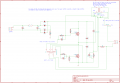
I have been reverse engineering the ultrasonic generators to see if I could figure out a way to improve them, but after determining the schematic and getting values for all the components, I have fallen into a slump. I am not entirely sure how the circuit works past a point. As far as I understand, the diodes on the top left are being using to rectify the voltage, after which a transformer increases the voltage and the transistor setup causes the circuit to oscillate using feedback from the load (my research tells me ultrasonic transducers are similar to an LC circuit). Note the load (2 parallel transducers) connects to the two pins labeled "out" on the right side of my schematic.
Particularly, I am curious if some of you are familiar with the "push-pull" (i'm assuming) power transistor design that is being used in the middle of my attached schematic. Is it possible for me to tweak some resistor or capacitor values to get better performance? Thoughts and suggestions are welcome. I have verified all the connections, part numbers, and sizes to the best of my ability. I am considering making my own digitally controlled circuit to get the frequency I want instead of this 36KHz output I see from a scope.
Attachments
-
 103.8 KB Views: 229
Last edited:


