Facebook
 Google
 GitHub
 Linkedin
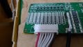
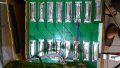
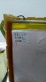
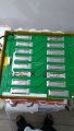
I acquired the battery in subject from one of the local recycle groups. It consists of nominally sixteen 3.2V 20Ah LiFePO4 pouch cells arranged in 8s2p configuration (pouches in pairs soldered to a PCB that puts them in series). One of the pairs developed a fault and was desoldered and removed by the previous owner. So my pack only has fourteen cells.
I'm brainstorming ways to use this to power my 12V inverter during power cuts. I have a charsoon antimatter hobby charger (that can balance charge up to 6 lithium cells, but will charge anything up to 30V), a 3D printer and a 30W soldering iron.
So far I've come up with the following ideas:
A. Solder a positive wire after the 4 top cells and use that half of the battery as a 12V 40Ah pack. Disadvantage is all the dead weight from the unused cells.
B. As above, but split the PCB to eliminate the bottom half of the cell. Disadvantages are that it's hard to cut a PCB at home (I was thinking of scribing and snapping so as not to make any dust), and the risk of mishaps in the process.
C. Remove all cells from PCB and re-make as a 4s3p pack (12V60Ah). This leaves only two unused cells. Disadvantages are that my low-power soldering equipment may not be up to the job, might overheat and destroy the cells, and I have no idea how to assemble the foil tabs into a pack (parts/tools/technique)
D. Put a shunt across the damaged cell position so the remaining cells becom a 7s pack, reconfigure the BMS wires for 7s, use the battery to drive a 500W 24V to 12V converter (they accept input voltages of 18-30V so 7s will still work). Advantages are that it makes the best use of the cells left in the pack. Disadvantages are that it requires a €25 voltage converter and a separate voltmeter to estimate battery SOC (since inverter only sees regulated 12V output), and the converter is only 90-95% efficient so we're looking at 50W of waste heat at 500W. Plus I don't know whether a DC-DC converter will drive an inverter input?
E. Use the top 4 cells directly as a 12V pack. Use the bottom 3 cells through a DC-DC boost converter to reach the inverter's minimum 10.5V input. Advantages are efficiency for the top cells while still using the whole battery. Disadvantages are having to switch inputs when the top cells are depleted.
Any feedback on the above ideas, or any new ideas will be most welcome")
I'm brainstorming ways to use this to power my 12V inverter during power cuts. I have a charsoon antimatter hobby charger (that can balance charge up to 6 lithium cells, but will charge anything up to 30V), a 3D printer and a 30W soldering iron.
So far I've come up with the following ideas:
A. Solder a positive wire after the 4 top cells and use that half of the battery as a 12V 40Ah pack. Disadvantage is all the dead weight from the unused cells.
B. As above, but split the PCB to eliminate the bottom half of the cell. Disadvantages are that it's hard to cut a PCB at home (I was thinking of scribing and snapping so as not to make any dust), and the risk of mishaps in the process.
C. Remove all cells from PCB and re-make as a 4s3p pack (12V60Ah). This leaves only two unused cells. Disadvantages are that my low-power soldering equipment may not be up to the job, might overheat and destroy the cells, and I have no idea how to assemble the foil tabs into a pack (parts/tools/technique)
D. Put a shunt across the damaged cell position so the remaining cells becom a 7s pack, reconfigure the BMS wires for 7s, use the battery to drive a 500W 24V to 12V converter (they accept input voltages of 18-30V so 7s will still work). Advantages are that it makes the best use of the cells left in the pack. Disadvantages are that it requires a €25 voltage converter and a separate voltmeter to estimate battery SOC (since inverter only sees regulated 12V output), and the converter is only 90-95% efficient so we're looking at 50W of waste heat at 500W. Plus I don't know whether a DC-DC converter will drive an inverter input?
E. Use the top 4 cells directly as a 12V pack. Use the bottom 3 cells through a DC-DC boost converter to reach the inverter's minimum 10.5V input. Advantages are efficiency for the top cells while still using the whole battery. Disadvantages are having to switch inputs when the top cells are depleted.
Any feedback on the above ideas, or any new ideas will be most welcome
Attachments
-
 2.1 MB Views: 5
 -
 2.5 MB Views: 6
Last edited: