OK, here is a real challenge that will be a design that you can sell and become obnoxiously wealthy. It does not need to be battery powered, though, and it could include integrated circuits if that made it better.
The device will not be a speech volume compressor, more like a smart volume expander.
The problem it will be solving is allowing the whole sentence to be heard when the folks with defective speaking abilities fade out on the last half of each sentence.
So the system will need to sense the volume level of the first words and then adjust the amplification to maintain that level until the pause at the end of the sentence or phrase. A standard volume compressor fails miserably because it boosts the gain during silence and then reduces the gain after one loud bit. So the speaker quickly reduces their amplitude of speaking and the whole phrase is lost. A standard volume expander circuit fails because it requires an increase in input level to provide a greater increase in output level.
So the system needs to sense the initial level and raise all that follows up to that same level. Quite a challenge, really. But try to avoid hard to locate single sourced components, because lots of these will be sold all over.
Another device that will provide even more profit AND make the creator a hero in the eyes of everybody who uses the telecom (telephone) system.
That would be a device that senses a spoofed caller ID signal and rejects the call. It needs to be compatible with standard home wireline connections, and internet phone modem connections, No other limitations.
Decoding GPS signals will require a whole truck load of transistors. And probably require a truck battery for power, if each transistor requires ten microamps.
Decoding GPS signals will require a whole truck load of transistors. And probably require a truck battery for power, if each transistor requires ten microamps.
So? It meet's the TS's spec. If the TS wants constraints on the designs to be suggested, it is up to them to supply some. Otherwise, we are shooting in the dark and he gets to live with the results.
Design a circuit that works with a line printer that prints out ideas for circuit design challenges.
Alternately, software for a computer or phone that does the same.
I think we need other constraints here. For example, design a faster than light speed space craft for mice
Have them travel for one year and then return to earth, see if they had attained human intelligence yet.
The system design I suggested in post #7 is certainly achievable, and with the relaxation allowing ICs in addition to transistors, possibly even fairly compact. In addition the market already exists so the product would sell.
"Warp-Drive", on the other hand, will require a bit of disruption in the time-space continuum, thus probably can not be achieved with transistors.
I realize this is probably not in the spirit of the original question but the “no ICs” provoked the thoughts about the debates of no MCUs. This sort of system might actually make some people happy since “programming” here has nothing to do with code. Compared to an MCU-based solution this is incredibly inefficient, but if it was designed with simplicity in mind, and a lot of boards for the mainboards and modules were made, it could be pretty cheap all the same.
In any case, here it is…
A general purpose, modular, programmable replacement for an MCU in those cases where simple logic is sufficient to solve the problem. It would comprise a bus with a standardized connector and a series of pluggable modules that provide I/O and/or logic functions allowing the building of a signal flow with inputs from sensors and switches, intervening logic and timers, and outputs to other modules or actuators/devices.
The bus would include power rails, of course. It would also have some number of discrete I/O channels (for output from modules). Each connector position would normally have these channels bridged (possibly with jumpers) but the
Example modules:
Input—these modules would accept a variety of signals and output conditioned results. For example, one might accept an analog signal from 0-10VDC and output a logical high when a settable threshold (trimmer on the board) is exceeded. Another might accept a logical level signal and buffer it, or do level conversion. A goal-stretchy one might accept 4 bits of input and trigger on a preset or more than one preset providing a logic high through N channels.
Output—these modules would interface with things off the board. They could be logic level outputs, 0-10V control outputs, PWM outputs (this would certainly make me want to allow ICs!), or even dry contacts—I am sure there is large number of useful outputs (and inputs for above, for that matter) that I am not thinking of.
Logic—simple gates, probably more than one per module that can be used to implement a truth table appropriate for the result. This could even take the form of a wire programmable thing using Dupont wires to determine signal flow though the gates on the board (also pluggable, so a logic module is just a host for these AND, OR, XOR, NOT, &c. gates). Clever design of the gate plugins might make them switchable with dip switches from AND to OR, etc.
Timer—these modules would just be like time delay relays allowing for delaying or extending signals as needed. In a more mature version, there might be sub-bus connectors on modules that accept these and other “conditioning“ modules so the output of the module encapsulates this functionality (to save space on the bus, etc.)
Filter—low-, high-, band- (&c) pass filters, notch filters, also possibly static threshold filters (e.g. <5V, >5V, &c). These could be used on the inputs or outputs.
This is by no means intended to be an exhaustive list, applying this system to problems will no doubt inspire other modules and the evolution of these. The basic idea in use is pretty simple—someone has sensors and actuators and wants—NO MCUs ALLOWED BUDDY—to have some logical relationship between the two.
I imagine the physical layout to be a mainboard and a many-pin-multipin bus connectors what allows the modules to be plugged in vertically—much like a PC expansion bus. Normally, there would be a dummy card in the slot that simply bridged the I/O channels (there would be an input and output of each channel at each slot so a module could control that channel, the dummy would just bridge these). The connectors for external connections on the Input and Output modules would be on the module itself, along the rear facing edge (again, like a PC).
Of course this would benefit from a proper card cage arrangement, mechanically.
So, an appropriate input module is selected. Its I/O channels are selected via jumpers on the board (if not hard wired).
This module has its own input connectors as above, and the sensor(s) are connected to these. If implemented, signal processing plugins might be included on the module.
A Logic module might be next on the bus, it would be configured so it’s input is on the output channel(s) of the Input module and if the signal from the input module was needed further down the line in uncooked form, its output was on a different channel for the next connection—otherwise, it would just send the cooked version downstream on the same channel.
Next an Output module is chosen, say a relay module. It would be plugged into the bus and configured so its input(s) was on the output channel of the logic module. The output of the Output module is primarily on the rear facing connectors but a bus-compatible signal could also be emitted so things further down the line could do more processing.
So, there it is—completely unnecessary but somehow it seems a polished version of this would be popular with the “NO CODE” sort of person. Of course, if we are treating the modules as black boxes then certainly small MCUs would begin to appear on them to deal with things like channel assignments and signal processing… then, larger, possibly dedicated MCU modules would be able to act as bus masters and… well you see where this is going.
(See attached image)
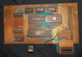
Funny you should mention this as I recently found my home built microcontroller board built with a Z80 at the heart of it. I was going through a lot of stuff and ran across it after it had been put away some years ago.
It's complete with a static RAM and UVEPROM. The UVEPROM holds the bootloader, which is a very simple set of code that allows uploading code to the RAM using a computer and just a custom serial connection. The logic chips perform the I/O functions and some address control.
I built this in the early 1990's or maybe a bit earlier (late 1980's) before microcontroller chips became more popular and EEPROM was either not available yet or very expensive. The bootloader code was very short and sweet, so instead of erasing the UVEPROM to update the bootloader, I was able to just program all zeros over the existing code and tag the new code higher up in the address space. During power up, the Z80 would see all nop's and then get to the real code. It would then wait for code from a computer or other device.
It was kind of fun to build and very useful, but I haven't used it in decades now. Even the simplest microcontroller chip could do more now.
Interesting indeed!! "Y" has described, in post #14, just a bit more than a logic system promoted back in the late 1950's I think. Or it might have been mid 1950's. It was called "CYPAK", and the modules were green plastic blocks with "Fast-on" style blades on one end. The basic technology was magnetic amplifiers and diodes.. They were a discreet logic replacement for relay logic, non-clocked but synchronized with the AC line somewhat. The system was quite reliable but also rather power hungry. and not at all compact..
And there's the rub.
It's not the circuit design that's the problem, its figuring out how to identify a spoofed call (which no one has been able to do).
One solution to the fake call would be to fight fire with fire, or rather, fight robot with robot.
Use Ai to answer the call and decide if it's real or not. Ha!
That would put an end to it until they got smarter yet.
There is no way this can be done with discrete parts though. No way. Probably easier to design an anti-gravity machine.
A second solution is to hire a secretary to answer all calls
Possibly that three-tone sequence used by the phone companies when one reaches an unassigned number would be a good starting response. It might result in no more calls if the calling computer recognized what it meant.
I have discovered that responding to the greeting some of them by reciting a string of numbers does give results in that they disconnect. But over half of them now are just silence.
In response to those wanting to sell medicare, I always was telling them that as I was only 42 years old, I did not qualify. That stopped them every time..
The ultimate fix will be for the ISP that receives the VOIP call to attach the sender's internet address to the caller ID string. Then it would be simple to reject calls based on address of origination. It would also require permanent banning of internet access providers that allowed spoofing of addresses.
 Facebook
 Google
 GitHub
 Linkedin
")