Thread Starter

Tridibeshhh

Joined Jun 25, 2022
13
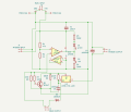
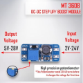
Hi, I made this schematic using Kicad. It's main job is to receive the input 5v4amp20watt power from my mobile charger and step it up to 7.5v using the mt3608 boost converter module (module's input connects to J1 and output connects to J2) and then use the voltage regulator and send the charging current to the external 4v 1amp sealed Led acid Battery I want to charge. It also has a red and green LED attach to it, so that when the battery is almost full (or the battery is removed) the green one lits up and red goes off.

Is it flawless (ignore the heat)
 

Attachments

B-JoJo-S

Joined Jan 3, 2026
605
Why are you boosting the voltage up before you drop it back down?

You start with 5V and end up with 4V. It would seem to me to be far less trouble to just buck the voltage down to 4V. Since you only want 1A a Buck converter should do the job you want.

From your schematic there are two inputs and two outputs. J1 & J2 - are they the Buck/Boost input and output points? J4, (Main Output) pin 2, I can't make out if it's positive or ground. J4-Pin 1 goes to pin 3 U1B LM358 while J4-Pin 2 comes from D3 (1N5819) which comes from R5 & C3. It doesn't look like it can work. Not to me anyway. But then again I'm not the one most versed in schematics and circuitry. I'm only a hobby level tinkerer. Two inputs - Two outputs - doesn't make it clear to me what this circuit does.
 
Last edited:

B-JoJo-S

Joined Jan 3, 2026
605
use the voltage regulator and send the charging current to the external 4v 1amp sealed Led acid Battery I want to charge.
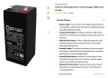
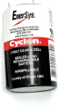
I've never heard of an SLA (Sealed Lead Acid) battery at 4V. 1A? Is that 1 Ah (Amp hour)? Sounds like a very specialized and small battery. What does that battery run? How much current does it draw? How long do you need it to run on a charge?
 

B-JoJo-S

Joined Jan 3, 2026
605
Found THIS
Screenshot 2026-10-29 at 7.44.44 AM.png
If you want to charge a 4V battery you need more than 4V. It looks like you might be trying to keep a fence charger battery topped off. An SLA battery is commonly 2.1V per cell, so it likely has only two cells. So now I've heard of a 4V SLA AGM battery. Your charge controller should not charge the battery above 4.6V (float charge). But charging it to 4V will never charge the battery to full capacity.

In a situation where I want to charge a 12V Lead Acid battery from a solar panel I'd use a panel that can produce up to 19V peak daytime volts. I'd buck that down to 13.8V. That way when the panel is producing far more voltage than needed the buck will hold the battery at its proper voltage.

I don't see a need for boosting 5V to 7.5V then bucking it down to 4V. Two reasons: First, you don't NEED 7.5V. A buck converter dropping voltage to 4V would do what you ask for. Second, 4V is not enough voltage to charge a 4V SLA AGM battery. Of course I'm pointing out the AGM thing because that's what I found on the web.

Please explain your purpose for 4V 1A beyond just charging a 4V battery. What are you wanting to do?
 

Ya’akov

Joined Jan 27, 2019
10,368
I've never heard of an SLA (Sealed Lead Acid) battery at 4V. 1A? Is that 1 Ah (Amp hour)? Sounds like a very specialized and small battery. What does that battery run? How much current does it draw? How long do you need it to run on a charge?
If it is a Hawker Energy Cyclon based battery (spiral electrode) it will have an open terminal voltage of 2V per cell. It would not be called an "SLA", though.
 

B-JoJo-S

Joined Jan 3, 2026
605
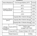
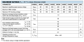
Digging deeper:
Screenshot 2026-10-29 at 8.05.58 AM.png
Down to the second to last table, charge voltage should be 4.52 to 4.6V for a float charge. See the link posted in post #4 to see the full spec sheet and other pertinent information.

Again, what is the Thread Starter (TS) wanting to accomplish? Does the TS want to use a 4V power supply to stand in for a 4V battery?
 

panic mode

Joined Oct 10, 2011
5,463
If it is a Hawker Energy Cyclon based battery (spiral electrode) it will have an open terminal voltage of 2V per cell. It would not be called an "SLA", though.
why would that be? many have it written right on it. word acid may not always show up but it is implied.
1793283262017.png
1793283710732.png
 

Thread Starter

Tridibeshhh

Joined Jun 25, 2022
13
Found THIS
View attachment 372809
If you want to charge a 4V battery you need more than 4V. It looks like you might be trying to keep a fence charger battery topped off. An SLA battery is commonly 2.1V per cell, so it likely has only two cells. So now I've heard of a 4V SLA AGM battery. Your charge controller should not charge the battery above 4.6V (float charge). But charging it to 4V will never charge the battery to full capacity.

In a situation where I want to charge a 12V Lead Acid battery from a solar panel I'd use a panel that can produce up to 19V peak daytime volts. I'd buck that down to 13.8V. That way when the panel is producing far more voltage than needed the buck will hold the battery at its proper voltage.

I don't see a need for boosting 5V to 7.5V then bucking it down to 4V. Two reasons: First, you don't NEED 7.5V. A buck converter dropping voltage to 4V would do what you ask for. Second, 4V is not enough voltage to charge a 4V SLA AGM battery. Of course I'm pointing out the AGM thing because that's what I found on the web.

Please explain your purpose for 4V 1A beyond just charging a 4V battery. What are you wanting to do?
My goal was to keep it exceptionally cheap, cheaper than the ZK 4KX also avoiding huge trade offs.
With R5 = 240 Ω and R2 = 680 Ω , the LM317 output can be set between about 4.5 V and 5.0 V. A 4 V (2-cell) lead-acid battery wants about 4.55-4.6 V for float charging, so the range works. After the 1N5819 drops roughly 0.2 V, the battery sees about 0.2 V less than the LM317 output.
The BC547 turns on at about 0.6 V across Rs, so the limitt is 0.6 V ÷ 3.3 Ω ≈ 180 mA, not 1 A. That’s right for a 1 Ah battery, because charging a small SLA at 1 A would overheat it. I'm Expecting roughly 6-8 hours for a full charge.
The LM317 dissipates about 0.5 W at 180 mA, so it doesn’t need a big heatsink (tho I'm adding one, and this is the only consequence for going this cheap). The 5 V 4 A charger is far more than needed, since the circuit draws only about 0.35 A from it.
1N5819, It stops the battery from draining back through the MT3608 when the USB power is off.

Setting the MT3608 to 7.5 V with nothing else connected. Then, with no battery attached, adjusting the trim until the LM317 output reads about 4.8 V. That puts the battery at about 4.6 V once the charge current tapers off, which is safe to leave connected indefinitely. Not going above about 4.9 V at the battery.
 

panic mode

Joined Oct 10, 2011
5,463
for small voltage drop, LDO will be simplest and cheapest. LM317 is linear regulator bit it is not low drop. it needs 2-2.5V overhead. a good LDO only need 0.05-0.2V overhead. with that there is not need to boost voltage.

for example MIC47100YMMETR is 1A LDO with only 80mV drop, MAX38913AANC+T is only 30mV etc.

for your application i would look into MIC29302 or LT1086 (Adjustable)
 
Last edited:

kiroma

Joined Apr 30, 2014
333
When regarding to a charger, if you want a practical thing, use a dedicated circuit/IC to do the task.
Only if you want to build your own charger and test in several ways that you should try to build (and of course study how to build) your own.
Attempting to build something you don't fully understand while dealing with chemistry can cause fires, up to burning your house down during unsupervised charging.

There's, at least for li-ion, chargers that you regulate the final current, the starting current, and other things. It's cheap, it's on Aliexpress. For lead-acid batteries I never searched about, but as common as they are, I don't doubt there's things for it too.
 

kiroma

Joined Apr 30, 2014
333
My goal was to keep it exceptionally cheap, cheaper than the ZK 4KX also avoiding huge trade offs.
If there's an affordable charger from China, I'm pretty sure you can't go cheaper than that. Just search before continuing.
If there isn't, the more inefficient your charger is with linear power supplies, the more you'll waste money on heatsinks too. So then you see that the best option is to go switched mode and be efficient. I'd search for an IC that does that and implement the circuitry around it that the datasheet suggests, with little modifications for my use.
 

MisterBill2

Joined Jan 23, 2018
28,584
Certainly that is a complex scheme to charge a battery!!
The important thing to understand is that to force a charge INTO a battery the charging voltage MUST BE GREATER than the voltage the battery is to be charged to.
We are not given the intended charge current by the TS, so I am going to GUESS charging at some low current.
So to avoid a lot of complication, use a 100 OHM half watt resistor to limit the charge current from the 5 volt source into the four volt battery. Connect the battery negative terminals together. The 4 volt battery will charge slowly. The resistor will cost less than the more complex circuit shown earlier.
THAT is as simple and cheap as I can create a simple battery charger, GIVEN NO ADDITIONAL INFORMATION, such as recommeneded charge voltage and current. Certainly it may not be very efficient, using a series resistor to control the charge, but if the supply voltage is not over the allowed float charge voltage,it should work.
 
Last edited:

Thread Starter

Tridibeshhh

Joined Jun 25, 2022
13
Certainly that is a complex scheme to charge a battery!!
The important thing to understand is that to force a charge INTO a battery the charging voltage MUST BE GREATER than the voltage the battery is to be charged to.
We are not giventhe intended charge current by the TS, so I am going to GUESS charging at some low current.
So to avoid a lot of complication, use a 100 OHM half watt resistor to limit the charge current from the 5 volt source into the four volt battery. Connect the battery negative terminals together. The 4 volt battery will charge slowly. The resistor will cost less than the more complex circuit shown earlier.
THAT is as simple and cheap as I can create a simple battery charger, GIVEN NO ADDITIONAL INFORMATION, such as recommeneded charge voltage and current.
Please see the post #8
 

B-JoJo-S

Joined Jan 3, 2026
605
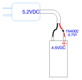
I've measured a few 5V Wall Warts (WW's). They usually come in at 5.1 to 5.2 volts. Adding a simple diode with a 0.7Vf should drop the voltage to 4.5 volts.
 
Last edited:

MisterBill2

Joined Jan 23, 2018
28,584
Certainly it takes a higher voltage to force a charge current into a battery. And the charge related properties of most battery types are neither simple nor linear nor independent of other variables, such as temperature and the present state of charge.
I've measured a few 5V Wall Warts (WW's). They usually come in at 5.1 to 5.2 volts. Adding a simple diode with a 0.7Vf should drop the voltage to 4.5 volts.
My guess is that you measured the NO LOAD voltage of those devices. Depending on the current rating, and the internal resistance, there will be some voltage drop as they supply current, UNLESS they include internal voltage regulator circuits. AND, most of those devices also mention a specific current as well.
EVERY NON-REGULATED supply voltage will drop when current is drawn, and most applications for external power sources require current to be delivered to some sort of load.
 
Top