Fixx,
I just remembered I have some of those Avoidance Sensors and a High/Low input relay module.
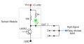
When the sensor out is High current will flow through the 10K resistor and the green status LED meaning the LED stays illuminated although much dimmer. The relay module still activates OK but you will noticed the LED is still slightly on. Just a heads up.
Below is the actual schematic for the output section.
Open collector? That means it would provide ground for the relay. From the drawing if I recall correctly you either see a "Low" or "Open". With the diodes and swapping the power connections to the relay it should work.
Here's what stumps me - the system works with a single sensor. But when multiple sensors are incorporated it doesn't. Have to wonder if there's a wiring error between the single setup and the multiple setup. If you use a pull-up resistor for each sensor then all three doors will have to be open for a true output to occur. Otherwise two doors closed will hold the relay at ground and prevent it from activating. I think the sensors are in combat mode. Each preventing the other from working unless all three sensors are in agreement.
See my explanation in post #48. One explanation was that the LM393 comparator output transistor could not pull down adequately with three pull up resistors. The max sink current for the LM393 is given as 16 ma, with a minimum capability of 6ma.
And while the performance with two devices connected was apparently satisfactory, I did not see that the check was dome with three devices. Or maybe I missed it?
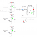
You guys are driving me silly. The schematic below shows the exact components used for the relay module, the sensor Out circuit and how they were connected by the TS.
When any door is closed the relay is activated, however the TS was using the NC contact so the LED lights were OFF.
Using only one sensor it works but the relay is activated most of the time since the doors are normally closed.
Now with all 3 sensors connected and even with the diodes installed it's makes up an AND circuit. So all three doors must be open to deactivate the relay and turn the lights ON which is the original problem.
It needs to be converted to a OR circuit by reversing the diodes and using a relay module with a High signal input. See post #62.
With the OR arrangement the relay is normally OFF until any door is opened and the lights will be moved to the NO contact.
I'm struggling with the basic concept here, I must be misunderstanding something. When you open a door infrared (natural?) light comes in hits the sensor, and turns on a closet light that feeds light back into the sensor, latcing the system on all night. You don't want that. Maybe that's actually a motion sensor, but the ones I've been using all go "high" to three volts even when the supply is 5 volts. Which brings me to another thought. Looking at the relay coil driver transistor and without studying further, I've personally had a lot of frustration trying to drive 5 volt relay coils on a 5 volt supply using transistors and mosfets that won't go well into saturation. They can be unexpectedly fickle. I've had slight better luck using a 3 volt coil with a resistor of a few ohms rated to take the current, and a 5 volt supply. Hope this helps.
I'm struggling with the basic concept here, I must be misunderstanding something. When you open a door infrared (natural?) light comes in hits the sensor, and turns on a closet light that feeds light back into the sensor, latcing the system on all night. You don't want that. Maybe that's actually a motion sensor, but the ones I've been using all go "high" to three volts even when the supply is 5 volts. Which brings me to another thought. Looking at the relay coil driver transistor and without studying further, I've personally had a lot of frustration trying to drive 5 volt relay coils on a 5 volt supply using transistors and mosfets that won't go well into saturation. They can be unexpectedly fickle. I've had slight better luck using a 3 volt coil with a resistor of a few ohms rated to take the current, and a 5 volt supply. Hope this helps.
The sensor consists of both exciter/transmitter and receiver. Does not use ambient light. When door is closed the doors surface reflects the IR back to the sensor. Door open, no reflection. This sensor works all day and night, no ambient light at night.
The sensor consists of both exciter/transmitter and receiver. Does not use ambient light. When door is closed the doors surface reflects the IR back to the sensor. Door open, no reflection. This sensor works all day and night, no ambient light at night.
Looking at the photo in post #1 it is difficult to see how that sensor operates. That is different from the door blocking the beam. If the door closed output is a logic low, then there must be isolation buffers added because if they are just in parallel then any one device pulling low will keep the light from switching on because three pull-downs will keep the signal low if any one is low. and diode isolation will not solve the problem.
This is another example of how incomplete information prevented an early solution to a the problem.
The problem early on was assuming that the Relay Module required a High input. If that had been true then post #2 would have fixed the problem.
It wasn't until post #31 that I realized the module required a Low input and several fixes were presented at that time.
ALL of the important information was missing from the initial post! This included that the sensor devices were active low output types with a resistor pull up, and also that the relay module was being operated in a reverse logic mode.
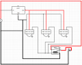
That's what was presented. Source negative goes to the bottom of IC1. Assuming it's connected to pin 1, the relay is connected to pin 1 and all three grounds of the sensors are connected to pin 1 (or common). Pin 2 of IC1 is clearly connected to VCC. Data lines all go to the other end of the relay. Even the diode shows polarity back to the negative of the PS. One can only assume the relay input was going to be a high in order to toggle it. The schematic is not well drawn but one can infer from pins 2 and 3 that all other connections are to pin 1.
That's what was presented. Source negative goes to the bottom of IC1. Assuming it's connected to pin 1, the relay is connected to pin 1 and all three grounds of the sensors are connected to pin 1 (or common). Pin 2 of IC1 is clearly connected to VCC. Data lines all go to the other end of the relay. Even the diode shows polarity back to the negative of the PS. One can only assume the relay input was going to be a high in order to toggle it. The schematic is not well drawn but one can infer from pins 2 and 3 that all other connections are to pin 1. View attachment 294247
The drawing I posted was taken from his post in #1. I just rearranged some of the ground wires to clarify what was my interpretation of his drawing. The indication from the schematic is that the sensors put a positive output when triggered. (active high).
You guys are driving me silly. The schematic below shows the exact components used for the relay module, the sensor Out circuit and how they were connected by the TS.
When any door is closed the relay is activated, however the TS was using the NC contact so the LED lights were OFF.
Using only one sensor it works but the relay is activated most of the time since the doors are normally closed.
Now with all 3 sensors connected and even with the diodes installed it's makes up an AND circuit. So all three doors must be open to deactivate the relay and turn the lights ON which is the original problem.
It needs to be converted to a OR circuit by reversing the diodes and using a relay module with a High signal input. See post #62.
With the OR arrangement the relay is normally OFF until any door is opened and the lights will be moved to the NO contact. View attachment 294159
The circuit is missing a resistor(like Rbe or adding a pull-up resistor on the common pin of diodes) to turn off the PNP transistor when the inputs of three diodes are all on high levels, so the common pin of diodes is on the floating status.

 Facebook
 Google
 GitHub
 Linkedin