How to use multiple IR avoidence sensors?

Thread Starter

Fixx

Joined May 9, 2023
19
I bought IKEA led lamps for my IKEA PAX wardrobe but needed IKEA LED driver is not in sale in my country. So I have to set up a system. LEDs are 24V, 1W, total of 3 LEDs.

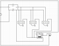
Since I'm setting up my own system, I also want to add automatic light up functionality when door of closet is open, my PAX closet has 3 doors, so any of them open also light up all LEDs.

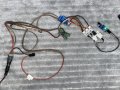
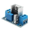
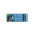
I'm using 24V SMPS PSU, LM317 voltage regulator, 5V relay and 5V IR avoidence sensor.

I can successfully managed my goal with only one sensor connected, but when I connect 2 or 3 sensor "OUT" pin together, it doesn't work.

I tried to draw a circuit but please accept my apologies in advance because I'm not an expert.

Also LM317 with heatsink is heating too much, like 60-75C, little current but regulating 24V to 5V. What alternatives can I use which is not heating? XL4016E1? XL6009?
 

Attachments

dendad

Joined Feb 20, 2016
4,641
For your power supply regulator, look for a "Buck Converter" switch mode regulator.
1683672085742.png
That will fix your heat problem.
Then, add a 1N4007 diode anodes to the data line of each sensor, and all 3 diode's cathode (stripe) connected together to the relay.
1683672897320.png
 
Last edited:

Ya’akov

Joined Jan 27, 2019
10,259
Welcome to AAC.

The solution above looks good. If it still doesn't work it could be due to the voltage drop across the diodes. You might need to use a Schottky diode, like a 1N5819 for its smaller voltage drop.
 

Thread Starter

Fixx

Joined May 9, 2023
19
Thanks for your help. I've passed to MP1584 buck converter and solved the heating issue.

But data issue continues. I tried both normal and Schottky diodes, tried two polarity for diodes, but no luck.

When only 1 IR sensor connected, it works as intented, both with and without diode.

When 2 or 3 IR sensors connected, I need to open all doors in order to activate the relay, both with and without diodes.

Maybe I need to put additional diodes to GND or VCC of IR Sensors? Any suggestions?
 

wraujr

Joined Jun 28, 2022
260
Your relay module has a VCC input (next to IN and GND), have you connected this VCC to the output of your Buck Converter (same connection as VCC to all your sensors)? It needs the VCC to power the transistor drive to relay coil.
 

Thread Starter

Fixx

Joined May 9, 2023
19
The diodes should have worked. Can you post a photo of the wiring and setup?
I installed IR sensor to wardrobe so i cannot easily detach them and take photo, but wiring is basically this and 2 another IR sensor sharing the VCC&GND. OUT lines also shared or divided to three diodes like this photo, no change in behaviour.
 

Attachments

dendad

Joined Feb 20, 2016
4,641
After a look at the IR board on Ebay, it looks like the output is active LOW.
And the relay is active HIGH. An extra stage of inversion will be needed.
 

Thread Starter

Fixx

Joined May 9, 2023
19
After a look at the IR board on Ebay, it looks like the output is active LOW.
So, the relay needs to be powered from +v, not gnd, and then reverse the diodes.
So disconnect the relay's GND pin, only VCC and IN pins intact?

Tried: Relay is not working without GND connected.
 

sghioto

Joined Dec 31, 2017
8,634
After a look at the IR board on Ebay, it looks like the output is active LOW.
And the relay is active HIGH. An extra stage of inversion will be needed.
I don't think so. When the doors are closed the output from the sensors should be low and go high when opened so the original diode application should work if installed correctly.
Fixx, measure the output of the sensor with the door closed.
I only see two diodes and can't tell the polarity because of the heat shrink.
 

dendad

Joined Feb 20, 2016
4,641
I don't think so. When the doors are closed the output from the sensors should be low and go high when opened so the original diode application should work if installed correctly.
Ah yes.
I was thinking one sensor at a time is operated but all will be with the doors closed.
Do the sensors output a voltage when off or are they open collector? A board circuit would help.
If in doubt, add a 1K resistor on each sensor from the +5V to the output pin.
 

Thread Starter

Fixx

Joined May 9, 2023
19
Circuit works perfectly with 1 sensor, like in the photo. But when I attach 3 sensors, doesn't work; relay off until all 3 doors are open, then relay on. I need relay on with any door open.

Door closed: LOW - Door open: HIGH

There is 3 separate diodes, I tried both polarity, but no luck.
 

sghioto

Joined Dec 31, 2017
8,634
Do you have another sensor you can wire up in the setup to test using both as in the photo?
I only see two white connectors with diodes (I assume), where is the output of #3 connected?
 
Top