An Arduino would be a fine addition as then extra functions could be added easily, like an alarm if the doors are left open, and a light timeout timer.....
It could be a good learning project.
Do we have any information available about the output of that IR sense module? Something does not seem to be right with the problem as stated, A correct diode isolation should have worked correctly. So someplace something is not as stated. An error, in other words.
That was stated back in post #33. Output is Low when the doors are closed. Problem is the relay module requires a Low input to actuate. Using diodes in this situation will not isolate the sensors.
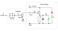
If the TS wants to use the modules listed then an inverter ( npn transistor ), 3 diodes and possibly a resistor will be required.
That was stated back in post #33. Output is Low when the doors are closed. Problem is the relay module requires a Low input to actuate. Using diodes in this situation will not isolate the sensors.
If the TS wants to use the modules listed then an inverter ( npn transistor ), 3 diodes and possibly a resistor will be required.
That is not nearly enough information. Is the output sinking or sourcing, what voltage? What current capability?? High and low are only a small part of the description. With a complete description both the problem and the best solution should be clear, at least to some.
The sensor module uses a LM393 comparator and does not have the current to sink or source in order to activate a relay directly hence the need for the relay module.
The sensor module uses a LM393 comparator and does not have the current to sink or source in order to activate a relay directly hence the need for the relay module.
OK, the LM393 comparator is an open collector device, meaning it has an external resistor pull up. So it is possible,even likely, that any one output transistor is not able to pull down against three pull up resistors in parallel.
That would have been verified if the measurements I asked for had been provided. So it will work to provide a buffer for each sensor. Use a CD4049 for inverting or a CD4050 for non-inverting. And then diode or gate to drive the relay.
It would need to have three transistors because the diode OR function can not be used directly at the outputs because it does not avoid the problem described in the #48 post. Each output needs to be buffered separately, so that there is not the problem caused by three pull-up resistors against one transistor. THAT seems too be why one works but three connected does not work..
That is why I asked for more measurements instead of just guessing that "High" and "Low" were exactly what they should have been. And the IC device that I suggested draws much less input current than the transistor circuit suggested
It would need to have three transistors because the diode OR function can not be used directly at the outputs because it does not avoid the problem described in the #48 post. Each output needs to be buffered separately, so that there is not the problem caused by three pull-up resistors against one transistor. THAT seems too be why one works but three connected does not work..
That is why I asked for more measurements instead of just guessing that "High" and "Low" were exactly what they should have been. And the IC device that I suggested draws much less input current than the transistor circuit suggested
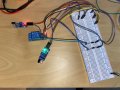
With one sensor and relay:
Sensor VCC: 5.11V
Sensor out(no obstruction): 5.11V (LED off)
Sensor out(with obstruction): 0.11V (LED on)
Relay activated when IN LOW
Relay ON IN connector: 0.25V
Relay OFF IN connector: 5V
With two sensor and relay:
When Both sensor's LED off, relay is OFF, 5V
When both sensor's LED on, relay is ON, 0.12V
When any sensor's LED on, relay is ON, 0.22V
With two sensor, relay and diodes:
When Both sensor's LED off, relay is OFF, 4.70V
When both sensor's LED on, relay is ON, 0.80V
When any sensor's LED on, relay is ON, 0.88V
Relay is always OFF when reverse the diodes. When I short sensor's GND and OUT, it's LED lights up.
I can't see how a HIGH active relay solve this issue?
With one sensor and relay:
Sensor VCC: 5.11V
Sensor out(no obstruction): 5.11V (LED off)
Sensor out(with obstruction): 0.11V (LED on)
Relay activated when IN LOW
Relay ON IN connector: 0.25V
Relay OFF IN connector: 5V
With two sensor and relay:
When Both sensor's LED off, relay is OFF, 5V
When both sensor's LED on, relay is ON, 0.12V
When any sensor's LED on, relay is ON, 0.22V
With two sensor, relay and diodes:
When Both sensor's LED off, relay is OFF, 4.70V
When both sensor's LED on, relay is ON, 0.80V
When any sensor's LED on, relay is ON, 0.88V
Relay is always OFF when reverse the diodes. When I short sensor's GND and OUT, it's LED lights up.
I can't see how a HIGH active relay solve this issue?
Your sensors are 5.11V when a door is open (HIGH). You want the light to turn on when a door is open; hence you need a HIGH active relay.
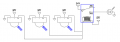
In order to turn the light on when ANY door is open, you need a HIGH output when Door 1 OR Door 2 OR Door 3 OR ANY door is open. This is an OR function and can easily be done with diodes with the cathode on the light (or load) side. But the circuit that turns on the light must respond to a HIGH signal. There are two ways to accomplish this.
Use an active HIGH relay or relay module
Use an inverter with an active LOW relay module. This can be simple as an NPN BJT or N-channel MOSFET, perhaps with a reverse biased diode across the relay coil terminals and maybe a resistor or two
With an active LOW relay module, if you open any one door, the other sensors are outputting a HIGH signal, and either of the others will illuminate the lights (in an OR configuration).
Open collector? That means it would provide ground for the relay. From the drawing if I recall correctly you either see a "Low" or "Open". With the diodes and swapping the power connections to the relay it should work.
Here's what stumps me - the system works with a single sensor. But when multiple sensors are incorporated it doesn't. Have to wonder if there's a wiring error between the single setup and the multiple setup. If you use a pull-up resistor for each sensor then all three doors will have to be open for a true output to occur. Otherwise two doors closed will hold the relay at ground and prevent it from activating. I think the sensors are in combat mode. Each preventing the other from working unless all three sensors are in agreement.
Here's what I'm trying to say: (assuming a 5V relay). With open collectors you can use a higher voltage relay. But that comes with higher current and the PIR's might not be able to sink that much current to ground.
There's an easy alternative:
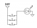
No sensors, no diodes, no relays. Just three parallel Momentary Open switches, 24VDC and the LED (assuming you've already dealt with current limiting for your LED's). All three doors closed then all three switches are depressed (open) and no light. Open any door or doors and the LED comes on.
Again, for those who read pictures better than words - I did not include a current limiting resistor because we know nothing of how the LED is built.

 Facebook
 Google
 GitHub
 Linkedin