How to use multiple 8038 function generators simultaneously?

Thread Starter

jsandin

Joined Mar 3, 2015
14
Hello...I'm new here. I tinker with electronic music devices, and I am trying to build a one-octave organ with 13
function generator ICs: 8038.
(I know there are better ways to build an organ,
but I want to do it this way because I have a bunch of these ICs).

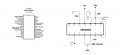
I have one of these ICs working just fine, with a trimpot for adjusting pitch, on a breadboard. See attached schematic, accompanied by a pin explanation for the IC.

My question: How do I connect more than one of
these ICs to a single power supply (+-9v), so that I
get multiple tunable outputs?
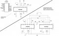
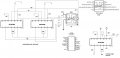
I have two of them wired up on a breadboard, with
a trimpot on each to control the pitch. The two ICs share a +- 9V supply. I can
vary the pitch with each trimpot, but there is
only one voice heard.
I've looked for a schematic containing more than
one 8038, but can't find any.
I'm hoping there's an easy answer. I'm attaching my schematic for a single instance; it works.

Thanks!
 

Attachments

GopherT

Joined Nov 23, 2012
8,009
@jsandin
I assume you are connecting these to one speaker. You need to put a resistor in series with each chip's output and connect those resistors to an amplifier (LM386 for example). Or you can connect them to an op-Amp in a standard inverting format as a pre-amplifier before you send the signal to a real studio amplifier. This will add the signals. Without, the signals will battle and could exceed sink or source currents and damage the chips.

Google: Adder Circuit Op Amp
 

Thread Starter

jsandin

Joined Mar 3, 2015
14
@jsandin
I assume you are connecting these to one speaker. You need to put a resistor in series with each chip's output and connect those resistors to an amplifier (LM386 for example). Or you can connect them to an op-Amp in a standard inverting format as a pre-amplifier before you send the signal to a real studio amplifier. This will add the signals. Without, the signals will battle and could exceed sink or source currents and damage the chips.

Google: Adder Circuit Op Amp
Sorry I didn't show it, but there is a 10k resistor in series with the sine and square wave (audio) outputs. And that will be the case with all the ICs I use. I think the term for what I'm attempting is "fixed resistor mixer". The output will go to a guitar amp, for starters. And thanks for the Op Amp suggestion.
 
Last edited:

Thread Starter

jsandin

Joined Mar 3, 2015
14
I'm creating a schematic for my failed attempt to get two of these ICs working off the same power supply and sounding two different notes. I'll post it asap
 

GopherT

Joined Nov 23, 2012
8,009
I'm creating a schematic for my failed attempt to get two of these ICs working off the same power supply and sounding two different notes. I'll post it asap
If you are familiar with a microcontroller, you might want to try connecting a microcontroller to an 8-bit programmable sound generator (AY-3-8910, AY-3-8912 or AY-3-8913). You get 3 channels of voice out of each chip. Each v0ice is a frequency, with programmable attack and decay with an overlapping level of 'noise'. Output is 16 bits but logarithmic so you get a pretty good dynamic range. One crystal in the 3 MHz range is used and the chip takes various divisions of that crystal frequency to make all sounds. The datasheet tells you which specific binary inputs will make each musical note if you want to make music.

It is an old-school chip but 8-bit keeps it very understandable for a beginner.
 

Thread Starter

jsandin

Joined Mar 3, 2015
14
If you are familiar with a microcontroller, you might want to try connecting a microcontroller to an 8-bit programmable sound generator (AY-3-8910, AY-3-8912 or AY-3-8913). You get 3 channels of voice out of each chip. Each v0ice is a frequency, with programmable attack and decay with an overlapping level of 'noise'. Output is 16 bits but logarithmic so you get a pretty good dynamic range. One crystal in the 3 MHz range is used and the chip takes various divisions of that crystal frequency to make all sounds. The datasheet tells you which specific binary inputs will make each musical note if you want to make music.

It is an old-school chip but 8-bit keeps it very understandable for a beginner.
Well, I want to finish this project, if possible, using the 8038 because (believe it or not) of some sentimental value regarding a 8038-based sound device my pal found 30 years ago, that I recently restored.
 

Thread Starter

jsandin

Joined Mar 3, 2015
14
GopherT

I appreciate the diagram! I'm going to assume the use of an LM386, per your suggestion earlier; I think I have one.

A few questions, although I think I know the answers already:

Q: Do V1-V4 indicate the audio outputs of the ICs?

Q: Do R1-R4 indicate the 10k resistors I'm using as a fixed resistor mixer?

Q: Does 0V indicate ground?

Q: Is 100K a good starting point for Rf?
 

#12

Joined Nov 30, 2010
18,224
I think I spotted another mistake. You're making them share a timing capacitor. Wrong move. Each chip needs its own timing capacitor.
yes, yes, yes, That will give you a voltage gain of 10. Try a 10k for a voltage gain of 1.

Correcting Gopher...connect the op-amp to +9V and -9V power supplies like you did with the tone generators. The positive input pin goes to the center of the supply voltages, which is allegedly zero volts.

The basic premise of the Adder circuit is to get all the signals to combine without fighting and without losing amplitude by feeding back through every body else's resistor.
 

Thread Starter

jsandin

Joined Mar 3, 2015
14
I don't have an LM386 (audio amp)
I think I spotted another mistake. You're making them share a timing capacitor. Wrong move. Each chip needs its own timing capacitor.
yes, yes, yes, That will give you a voltage gain of 10. Try a 10k for a voltage gain of 1.

Correcting Gopher...connect the op-amp to +9V and -9V power supplies like you did with the tone generators. The positive input pin goes to the center of the supply voltages, which is allegedly zero volts.

The basic premise of the Adder circuit is to get all the signals to combine without fighting and without losing amplitude by feeding back through every body else's resistor.
Thanks. Between you guys and Google, I sense success.

I don't have an LM386 audio amp, but I have these 8-pin ICs....
LM301
401 A UA741CP
G741 976
5532 (dual op amp)

Opinions, anyone...?
 

GopherT

Joined Nov 23, 2012
8,009
I don't have an LM386 (audio amp)


Thanks. Between you guys and Google, I sense success.

I don't have an LM386 audio amp, but I have these 8-pin ICs....
LM301
401 A UA741CP
G741 976
5532 (dual op amp)

Opinions, anyone...?
The 5532 is a nice, low-noise opAmp for musical applications. The fuzzy sound in the 386 would drive you crazy.

Do like #12 said. Use 2 x 9V batteries for power on the op amps and the mid point of that 18 volts as the ground (0 volts). The schematic I posted uses that midpoint as ground so you need -9 volts into pin 4 and +9 v into pin 8 of your 5532.

Also, how did you solve the problem, I assume it was #12's comment about the timing capacitor. I completely missed that.
 

#12

Joined Nov 30, 2010
18,224
Groan. :(
Those 741 chips are antiques. They can barely keep up with audio frequencies. Save them for blinking LEDs.
 

Thread Starter

jsandin

Joined Mar 3, 2015
14
The 5532 is a nice, low-noise opAmp for musical applications. The fuzzy sound in the 386 would drive you crazy.

Do like #12 said. Use 2 x 9V batteries for power on the op amps and the mid point of that 18 volts as the ground (0 volts). The schematic I posted uses that midpoint as ground so you need -9 volts into pin 4 and +9 v into pin 8 of your 5532.

Also, how did you solve the problem, I assume it was #12's comment about the timing capacitor. I completely missed that.
I haven't solved it yet. Tonight, I hope, with the advice I got from you guys, I'll get it working.
 

RichardO

Joined May 4, 2013
2,270
You have something important missing from your circuit. That is power supply bypass capacitors. You should place a 10 uf cap from +9 volts to ground and another 10 uF cap from -9 volts to ground. Then on each 8038 you should also put a 0.1 uf ceramic cap from the +9v to ground and -9v to ground. The 0.1 uF caps must be installed as close as possible to the 8038 power pins with short leads going to ground.

All of these caps are needed. If you don't install them the 8038 will not generate clean waveforms. In addition, with more than one 8038, the oscillators will have a tendency to lock to each other trying to run at the same frequency.
 
Top