How to trigger a relay based on a resistance drop in a Push to Start Switch

Thread Starter

Restomod

Joined Jan 17, 2026
70
OK - got the new diodes, made two boards, 5v on the outbound.

Still have the 1.74v and 1.2v at the switch connection - no relay actions and starting with the voltage discrepancy, they are all off.

at the 12 and 10 ohm connection, .25v and then off the LM393 1 and 7 pins, 0.19v


Is there a posibility the
 

sghioto

Joined Dec 31, 2017
8,737
You mean 12K and 10K ohms.
If there is only 0.25v at that junction then the resistor values are incorrect.
Same for the switch, should read 2.5 volts when not pushed, unless it's not really 1K ohms or R2 is not 1K.
 
Last edited:

Thread Starter

Restomod

Joined Jan 17, 2026
70
sorry yes those are 12k ohm, 10k ohm

I measured resistance and volts as I built it
There is a topic with the switch. While others in my presence also measured 1000 ohm open, ans 600 ohm closed when we started this project, I just measured the open resistance and the result is repeatable at 2.39k ohm, 600 ohm closed. I repeated this on both pins that the switch triggers, and did it ten times. No idea what could have happened.
 

sghioto

Joined Dec 31, 2017
8,737
I just measured the open resistance and the result is repeatable at 2.39k ohm, 600 ohm closed.
Something is still off, with those new values the voltages readings you measured previously are not adding up.
If the switch (R1) is 2.39K open and R2 is 1K then the voltage across the switch should be 3.52 volts and 1.875 volts when closed.
 

Thread Starter

Restomod

Joined Jan 17, 2026
70
Something is still off, with those new values the voltages readings you measured previously are not adding up.
If the switch (R1) is 2.39K open and R2 is 1K then the voltage across the switch should be 3.52 volts and 1.875 volts when closed.
The switch off the board a month ago measured 1000k and 600 ohm, how it changed now after weeks on the bench is a mystery.
 

Thread Starter

Restomod

Joined Jan 17, 2026
70
The switch off the board a month ago measured 1000k and 600 ohm, how it changed now after weeks on the bench is a mystery.
Added another multimeter to the collection to ensure that wasn't the issue - the switch has changed, could be we fried something inside?

Resistance open is 2.4kohm, and 605 ohm closed. Letting it sit on the powered board to see if it changes more...
 

sghioto

Joined Dec 31, 2017
8,737
The 1.9V is fine with the switch closed as that is below the reference voltage of 2.27volts.
Are you reading 2.27volts at the junction of the 12K and 10K resistors?
 

Thread Starter

Restomod

Joined Jan 17, 2026
70
The 1.9V is fine with the switch closed as that is below the reference voltage of 2.27volts.
Are you reading 2.27volts at the junction of the 12K and 10K resistors?
2.28 I left it on all night, no changes


a friend suggested perhaps the LM2903 ilo LM393, thoughts?
 
Last edited:

Thread Starter

Restomod

Joined Jan 17, 2026
70
The LM393 is fine.
Is the circuit working or not?
no

it is just like two weeks ago
The second relay latches upon connection to 12v power

At the trigger (IGN SW) 3.5v open, 1.9v closed

at the 10 to 12 k ohm junction, the resistors measure correctly, no voltage change
 
Last edited:

sghioto

Joined Dec 31, 2017
8,737
The second relay latches upon connection to 12v power.
Possibly a shorted transistor.
You have correct voltages on the input of the LM393.
When the switch is open the outputs on pins 1 and 7 should be appx 0 volts and .7 volts when closed.
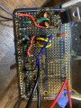
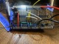
Can you post a photo of the actual circuit?
 

Thread Starter

Restomod

Joined Jan 17, 2026
70
Possibly a shorted transistor.
You have correct voltages on the input of the LM393.
When the switch is open the outputs on pins 1 and 7 should be appx 0 volts and .7 volts when closed.
Can you post a photo of the actual circuit?
No response at pin 1 or 7 on switch closure

Getting a security error when attaching pictured
 
Top