How to start 74192 to load preset values

Thread Starter

brownoutee

Joined Jun 30, 2018
13
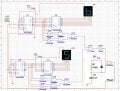
Hi guys im currently creating a 55 to 64 counter using a 74192 and i cant seem to make the counter to start at 55 i already set the preset values that i need but when i start the counter it always starts at 99.
i also tried connecting the BO pin to the load and it started at 55 but then the counter does not trigger the load when the counter counts to 64, cause i need it to start counting from 55 then when it counts to 64 it goes back to 55
when i do not connect the load pin to the BO it would start at 99 then 00 then it will count up to 64 when it hit 64 then it goes back to 55 and the circuit is ok i only need to make it start at 55 and i think then it is ok
thanks for anyone who can help55-64.png
55-64.png
 

ericgibbs

Joined Jan 29, 2010
18,766
hi b,
Welcome to ACC.
Checking your circuit you have a number of duplicated/redundant wires to the Load pins ??
I would suggest that you tidy the Load wiring and repost the circuit.
E
 

ericgibbs

Joined Jan 29, 2010
18,766
hi,
Thats easier to follow, the parallel data bytes and clocks look OK.
Have you measured the State of the Pload line [ U20A out] at power up.?
Is this problem happening in simulation or a real circuit.?
Another query, with a 200Hz clock how long will it take to count from 55 to 64.?
E
 

Thread Starter

brownoutee

Joined Jun 30, 2018
13
the U20A out is for the load when the counter is at 64 it does not do anything when i start the circuit
this happens in simulation im using multisim 14.1 im doing this cause i will buy the components to make the actual when the simulation is ok
dont mind the clock i just set that to 200hz cause the counter starts at 99,00 then it counts up, i just want it to count to 64 fast so i dont have to wait long
 

ericgibbs

Joined Jan 29, 2010
18,766
hi,
If you don't use a Pload at power On, the 74LS192's can initialise in an indeterminate state, it will not automatically Load the D pin inputs.
Consider adding a power On Pload pulse that is OR'ed with the counter output Pload from U20A.
While doing this test, disconnect the Clock and hold the Cup pin High, that should load 55
E
 

ericgibbs

Joined Jan 29, 2010
18,766
hi,
It is possible use a Res/Cap circuit.
This sim shows one option.
Did you measure the state of U20A output at power up.?
E
EDIT:
Do you follow this circuit OK.?
 

Attachments

Last edited:

ericgibbs

Joined Jan 29, 2010
18,766
hi b,
As this a Homework assignment we will not give the answers to problems, just clues or hints to help you complete the project.
Try adding that small circuit to your main circuit, post when ready, we can check it.
E
You can use a 74LS08 or AS08, in place of that HCT version I have used.
 

ericgibbs

Joined Jan 29, 2010
18,766
Did you measure the output of U20A, with the Clock disconnected and then Cup connected to +5V, I asked in post #6 and #8.
Please tell me what you measure, do you have a scope feature on your simulator.?
E

Rechecked on my LTS, it works OK.
 
Last edited:

ericgibbs

Joined Jan 29, 2010
18,766
Looking at your image it shows both counters set to '5' , which it is supposed to do.??
But you said it does not Pload, it must be loading OK.
So why do you think its not working.?
E
 

ericgibbs

Joined Jan 29, 2010
18,766
The scope probe maybe adding some capacitance to the Pload line and stretching the pulse.
For a test only add a 1no capacitor from the Pload line to 0V.

Which simulator are you using.?

AA1 30-Jun-18 15.15.gif
 
Top