 Facebook
 Google
 GitHub
 Linkedin
Hello guys. Thanks to the help of a lot of you, I've built a constant current source/sink circuit. ( See VCCS attachment). The circuit is an op amp + transistor current sink, and I'm using an H bridge stage to switch the direction of the current through the Load.
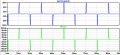
The circuit works with square pulses. They are in the range of 250-500µs(pulse width) and 20-100 Hz. Each time a pulse is delivered, the H bridge alternates polarity so that the next one flows in the opposite direction.
I would like to see the CURRENT waveform at the Rload, so that I can actually evaluate how well the circuit works. To do that, I'm using 2 oscilloscope probes, connected at each side of Rload, then, by sustracting Probe1 from Probe2, I get the voltage drop at RLoad, and since Rload is known, we can calculate the current, and "see" it in the oscilloscope.
I was wondering if there is another method applicable to my circuit to measure and see the current waveform, or is this the best way to go about this. Maybe somebody has had this problem before, I don't really think I can get my hands in a current probe, they are a little to expensive for me.
Thanks a lot for the help everyone!
Happy Halloween
EDIT: sorry about the double attachments.
Attachments
-
 135.3 KB Views: 53
 -
 147.2 KB Views: 48
 -
 147.2 KB Views: 27
 -
 135.3 KB Views: 34


