Measure the RMS value from the CT current sensor signal

Thread Starter

frank555

Joined Sep 30, 2024
6
I am using a CT current sensor to measure the current consumption of an AC device. Is there a relatively accurate way to get the RMS signal from the sensor? Because the sensor signal I put into the oscilloscope, I see that it is not a perfect sine wave, I make a circuit to take the peak amplitude and divide it by the root of 2, it is no longer accurate. I say it's not accurate because I measured the current with a clamp meter for comparison. The measurement results were about 50% different than what I measured with the clamp meter. I find the RMS value measured by the oscilloscope quite accurate and I think its calculation is more complicated. Thank you everyone.

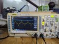
Here is an image of the waveform I measured.
 

Attachments

Thread Starter

frank555

Joined Sep 30, 2024
6
1) Sample at above 1600Hz. Square the value each sample. Do a running average with an IIR filter. Take the square root of the output.
or
2) Use an RMS-to-DC converter
https://uk.farnell.com/c/semiconductors-ics/data-signal-conversion/rms-to-dc-converters
Thank you for your helpful answer. What I'm aiming for is signal processing at the hardware level. Is there an opamp circuit that can calculate RMS signals or do I have to trade off by using a dedicated RMS calculator IC at a higher cost?
 

Ian0

Joined Aug 7, 2020
13,097
Thank you for your helpful answer. What I'm aiming for is signal processing at the hardware level. Is there an opamp circuit that can calculate RMS signals or do I have to trade off by using a dedicated RMS calculator IC at a higher cost?
It’s not easy to accomplish the “square” function with op-amps with any degree of accuracy. It generally involves a lot of very closely matched bipolar transistor, similar to the logarithmic and exponential amplifiers. Matched transistors are a lot easier to fabricate when they are all on the same chip.
https://patentimages.storage.googleapis.com/08/ab/84/99f50a6fbae9d0/US7081787.pdf
 

Thread Starter

frank555

Joined Sep 30, 2024
6
It’s not easy to accomplish the “square” function with op-amps with any degree of accuracy. It generally involves a lot of very closely matched bipolar transistor, similar to the logarithmic and exponential amplifiers. Matched transistors are a lot easier to fabricate when they are all on the same chip.
https://patentimages.storage.googleapis.com/08/ab/84/99f50a6fbae9d0/US7081787.pdf
Thank you for giving me more useful information. Maybe I have to accept the high price of my product in exchange for more accuracy in measuring current.
 

MrChips

Joined Oct 2, 2009
34,628
Examine the correct meaning of RMS, root mean square.

The RMS value of a signal represents the DC value that would have the same power as the signal in question.

This is determined by computing the square, mean, root. In other words, one computes the square, followed by the mean, followed by the square root.

The calculation of dividing by the square root of 2 applies to sinewaves. It does not apply to other random waveforms.

Before the advent of modern electronics, RMS could be determined accurately using a hot wire ammeter.

With MCU software solutions, the proper method of determining RMS is to do exactly as stated above. Take continuous samples, and compute the square and take the mean over a given period. Then compute the square root of the mean.

Sorry, there is no easy hardware solution.
 

Thread Starter

frank555

Joined Sep 30, 2024
6
Examine the correct meaning of RMS, root mean square.

The RMS value of a signal represents the DC value that would have the same power as the signal in question.

This is determined by computing the square, mean, root. In other words, one computes the square, followed by the mean, followed by the square root.

The calculation of dividing by the square root of 2 applies to sinewaves. It does not apply to other random waveforms.

Before the event of modern electronics, RMS could be determined accurately using a hot wire ammeter.

With MCU software solutions, the proper method of determining RMS is to do exactly as stated above. Take continuous samples, and compute the square and take the mean over a given period. Then compute the square root of the mean.

Sorry, there is no easy hardware solution.
I got it, thank you very much :3
 

ronsimpson

Joined Oct 7, 2019
4,646
True RMS measuring IC
AD737JRZ-RL
LTC1966CMS8#TRPBF
I like the 8 and 10 pin versions.

It looks like your load is a PC or TV or something like that. Use a heater or some resistive load to see a sine wave. You are getting current pulses at the peak of the sine wave. Very typical of a power supply with a full wave bridge as a load.
It also could be you don't have the burden resistor right.
1729089293759.png
 
Top