How to make a separate ground for MCU to measure with ADC

Thread Starter

ArakelTheDragon

Joined Nov 18, 2016
1,366
The zener diode can not be there. The whole point is that we measure the voltage drop accross the resistor R2. Otherwise the voltage applied to the ADC pin will be the same as the zener and it will never change. Yes this is my idea too, but with MOS transistors instead. In particular SI9926CDY.
 

cmartinez

Joined Jan 17, 2007
8,838
The zener diode can not be there. The whole point is that we measure the voltage drop accross the resistor R2. Otherwise the voltage applied to the ADC pin will be the same as the zener and it will never change. Yes this is my idea too, but with MOS transistors instead. In particular SI9926CDY.
I agree with dana that most ADC's nowadays work using differential signals, and make the use of a separate ground moot. But if you must have a separate ground, I suggest you take a look at dc-dc converters, such as this one. But the output of this kind of converter would have to be filtered somehow, because it's like a switched mode power supply, which are extremely noisy for their use in ADC circuits.
 

ScottWang

Joined Aug 23, 2012
7,504
The zener diode can not be there. The whole point is that we measure the voltage drop accross the resistor R2. Otherwise the voltage applied to the ADC pin will be the same as the zener and it will never change. Yes this is my idea too, but with MOS transistors instead. In particular SI9926CDY.
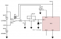
Yes, I just want to protects the ADC and almost forgot the zener diode will clamp the voltage which because R1 is there.

If you want to protect the ADC then you can use the circuit below, otherwise you just use your voltage divider.

Measuring.2.batteries.in.series.and.not.in.series_ArakelTheDragon_ScottWang-02.png
 

Thread Starter

ArakelTheDragon

Joined Nov 18, 2016
1,366
How can that be done? How do they do it on the arduino forum?

EDIT:
This is the circuit, I accept my chargers are with an isolated power supply (charger is ABC-1220D FST).

https://www.dropbox.com/s/zt3bkw6guij0etv/Battery.monitor.02.04.pdf?dl=0

I am trying to use a finder finder 32.21 x000 relay. But its rated for AC current and I can not find DC specification, can it be used, how much will the voltage drop be? Since I am measuring voltage it is important.
 
Last edited:

Thread Starter

ArakelTheDragon

Joined Nov 18, 2016
1,366
Here is the circuit. It will be turned on for about 30mS every 10minutes. After that it will enter sleep mode. I was thinking of a capacitor paralel to "R7" in pico farads in order to filter any noise from the switching or anything else. Also an opto transformer to separate the batteries from the MCU, so it can have a different ground, despite being powered from the batteries indirectly.

https://www.dropbox.com/s/j3z0hlacjeblf5a/Circuit.pdf?dl=0
 

ScottWang

Joined Aug 23, 2012
7,504
Please upload the circuits to our forum, otherwise when the site lose the connection then this part of thread will be become useless.
 

Thread Starter

ArakelTheDragon

Joined Nov 18, 2016
1,366
Thanks for the explanations, they are very useful. But the problem is already solved I will use the circuit below, what bothers me is will the relay transfer the voltage and current, epecially since this model is for AC I think?

I also have given 2 options for a power supply. With LM117 and LM2576, which do you think is good enough? And the "22pF" capacitor on the reset button bothers me.

Tomorrow I will soder it and test it.
 

Thread Starter

ArakelTheDragon

Joined Nov 18, 2016
1,366
Its working. I used a different transistor and switched it from "3.3V", because it was all I had. I used the LM 317 power supply, but I did not upload the whole code to the chip, because its long. So I only used the ADC code to test, without the wifi part. It was draining about 30mA. With the wifi code it might be more.
 

Attachments

Top