How to make a separate ground for MCU to measure with ADC

Thread Starter

ArakelTheDragon

Joined Nov 18, 2016
1,366
I have an MCU which will be measuring 2 batteries in series. The measured both in series and separated. When they are in series I can easily connect the MCU ground to the lower battery "-", but when they are separated I need some other ground to measure compared to. Can this be done with a wire connected to the metal frame of the battery bank and only the MCU ground?

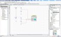
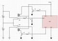
The circuit as promised:
https://www.dropbox.com/s/yuxkuf06l8xuopp/V.2.2.jpg?dl=0

Ark_V2.2.jpg
 
Last edited by a moderator:

Avid0g

Joined Apr 1, 2018
21
One possibility is that your MCU has enough precision and range to just measure both voltages and subtract in software.

If the voltages exceed the range (typically 5.00 volts), then a precision voltage divider can be used. Voltage dividers can be modified dynamically to bring an analog voltage into range.

Your MCU may have multiple analog inputs and/or you have an external analog multiplexer. This can be implemented with CMOS or relays.

You may also use a precision instrumentation op-amp circuit to translate differential voltages to a common mode voltage. This is especially useful when the two inputs to the translator are connected to an analog crossbar/multiplexer. This allows measuring reference voltages, or grounded inputs, and calculating the offset voltage and linear errors of the op-amp.
 

danadak

Joined Mar 10, 2018
4,057
Modern CPU A/Ds have differential inputs, some with muxes. Makes
this measurement trivial. PSOC, also has onchip reference and opamps
to condition incoming signals. Some even with DSP to filter them.


Regards, Dana.
 

danadak

Joined Mar 10, 2018
4,057
Basically you would use a V divider (2) to divide down the
V at the upper battery ground and another for its + terminal,
and feed that to internal PSOC diff mux. Then use another
channel where bottom battery gnd and its + terminal connected
to another A/D diff channel.

Then just measure each channel. The bottom channel is then the
V difference between gnd and the bottom battery + terminal. The top
channel is the V difference between its - terminal and the top battery
+ terminal.


Regards, Dana.
 
Last edited:

danadak

Joined Mar 10, 2018
4,057
An example, attached -

Ignore R values, they have to be computed to scale the max allowed A/D in
voltage.

By the way, as other poster pointed out this can also be done single ended,
just do an error budget for both cases to see which one you prefer. If you
do single ended you can stay with PIC UP. That choice depends on what
else you need to do, eg. chip capabilities. PSOC has a lot of mixed signal
in it, as well as arm core. Attached a list of on chip components.

Regards, Dana.
 

Attachments

Last edited:

Avid0g

Joined Apr 1, 2018
21
Oooo, this very difficult. Q3 has the gate and source tied together. As drawn, it cannot ever conduct. Q4 gate is tied to the bottom of Battery 7. I cannot read the voltage annotation above each battery. Please give us a table of battery number and voltage annotation.

I must assume that Q3 gate is not supposed to connect to the source, but elsewhere instead - like ground. That way only Q3 OR Q4 could conduct - But Not Both.

Can you see the one other requirement in order to bias Q3 or Q4 on? At the moment, the bottom of battery 7 May be floating.
 

Avid0g

Joined Apr 1, 2018
21
Maybe Q3 could conduct if the Gate was more positive than the Drain. What do you think could cause that ? Would Q4 already be conducting? Why would that be OK?
 

Thread Starter

ArakelTheDragon

Joined Nov 18, 2016
1,366
I wonder if it will work with 1 ground or will that just short circuit the batteries by connecting the upper battery's "-" to the lower battery's "-".
 

ScottWang

Joined Aug 23, 2012
7,498
I have only 1 ADC pin and 9 digital I/O pins as I am using an Amica Wifi module. This is the circuit that looks good to me, but it still takes 2 grounds.
Add Rbe1 and Rbe2 for Q1 and Q2 and across on their B, E to make the bjt turn off more quickly, because the relay of turn off time will be a little longer than turn on time.
Add a zener diode in parallel with R2 and the Vzd should be a little higher than Vmax of R2.
 

Thread Starter

ArakelTheDragon

Joined Nov 18, 2016
1,366
Thanks!

This is the charger that I will use.

EDIT:
This is the charger that I will use, it should work even when charging the batteries while they are connected in series.

Description of ABC-1220D FST:
Short-circuit Protection: Charger O / P cut-off automatically when short circuit. Overload Protection: Charger O / P current-limited automatically when overload. Reverse Polarity Protection: Charger O / P cut-off automatically when batteryreverse connection. Automatic multi-rate charging function: Equalizer Charge and Floating Charge. Parallel Operation Available: Parallel with Battery as DC Power Supply operation available. Unique LCD Display: Indicating both charger status and battery level. 3 LED Display: Red (Power On) , Green (Floating charge) and Yellow (Equalizer charge). Advanced SMD Technology: Reliable and Elegant.

Link:
https://www.battery-import.eu/p/fst-abc-1220d-12v-20a
 

ebeowulf17

Joined Aug 12, 2014
3,307
I have only 1 ADC pin and 9 digital I/O pins as I am using an Amica Wifi module. This is the circuit that looks good to me, but it still takes 2 grounds.
Why not eliminate relay 2, Q2, etc. and just read battery 1 voltage in one position, and (battery 1 + battery 2) in the other position. Then subtract battery 1 from (battery 1 + battery 2) readings in code to get the battery 2 reading.

Then you can use a single, common ground for everything. The only downside is it effectively cuts your ADC resolution in half, since you'll have to set your voltage divider resistances to scale things for a maximum of 2x battery voltage.

How precise do you need your battery measurements to be? What is the resolution of your ADC?
 

Thread Starter

ArakelTheDragon

Joined Nov 18, 2016
1,366
My ADC is 10 or 8 bits, I need to see the documentation again.
The accuracy will be fine, even with an 8 bit ADC, I have made the accuracy very good, when I was working n other projects.

I was thinking of reading the 12V and 24V dividers also, I think I did not post the other circuit. I am intending to use an NPN MOS instead of the BC547A. The problem that arrises from using this method is that if the batteries are disconnected, I am thinking the ADC might read the negative voltage from the lower battery as there is no real ground only "+" and "-". I realize that this is a DC circuit and it should be ok, but I am not curtain. I do not want -12V to be applied on the ADC, while the upper battery is disconnected. Maybe this can be overcame with a permanent series connection and a DPDT relay which will transfer not only the +power, but also transfer the lower battery's "-" to the MCU ground (which is the common "-" for all from the lower battery and is just the same).

Its a real problem. Thats why a MOS might be better because it conducts in 1 direction, but I dont have time to look for a circuit, because I have to be finished by Tuesday.

https://www.dropbox.com/s/r6hrg1h8k0xatms/66.V.1.2.jpg?dl=0

EDIT: I still wonder why cant the schassis ground be used (connect 1 wire from the MCU ground to the battery bank metal frame)? What is the SCHASSIS ground ment for?
 
Top