hi,
If you are getting 20V output for 8.4mV input, you have something incorrectly connected or a wrong value, thats a gain of ~2400.
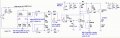
I need to see a complete circuit diagram which shows all the component values, so that I can check it out.
hi,
If you are getting 20V output for 8.4mV input, you have something incorrectly connected or a wrong value, thats a gain of ~2400.
I need to see a complete circuit diagram which shows all the component values, so that I can check it out.
dear eric,
i set the circuit for 0-2mv the amplifier output is 0-5V and V-i circuit output is 4-20mA so thats why i get those range.
i set Rg value 2k with 500 ohm trim pot
dear eric,
i set the circuit for 0-2mv the amplifier output is 0-5V and V-i circuit output is 4-20mA so thats why i get those range.
i set Rg value 2k with 500 ohm trim pot
hi rajit,
Do you appreciate that by using a single supply for the OPA's and the fact they are not rail to rail, there will always be a slightly positive offset above zero volts at Vout.??
To ensure a absolute zero voltage at Vout, the OPA's require a dual supply.
You may recall the initial purpose of the project was to give a 4mA thru 20mA current for a bridge voltage of 0mV thru ~2mV, which it does OK.
Why do you require a Vout of exactly 0v thru 5v.???
dear eric,
i just go for the positive supply alone for the reduction the number of voltage regulator in the power supply unit.
my task is to design the amplifier(0-5V) with 4-20mA output for low signal as a input source.
so i chose (0-2mV) as input. Example application strain gauge
hi rajit,
I understand, the problem is the OPA's, as you know there are rail 2 rail OPA's which will give a close to zero volts output, you are using an OPA which cannot go to zero with a single positive supply.
An actual zero volts out requires a negative supply for the OPA.
Who has set you this difficult task of 0V to 5V out.
Eric
dear eric,
yes eric frist i strat with 1-5V. because this circuit is more easy to replace the mosfet with my available components and provide some stable 4-20mA. once its test ok then only i try to modify the circuit with my requirement.
Morning rajit,
Using your existing OPA's with a single power supply, achieving a Vout of zero volts is not possible,
If you add a negative voltage supply and make other modifications, Vout=0 is possible.
Let me know what you decide and we can redesign the circuit.
BTW: The fact you have built the project using general specification OPA's and components and it works as well as it does, you should feel well satisfied with its performance.
dear eric,
before that i have a doubt, as per your suggestion of 1-5 V amplifier
can we set 1V amplifier output for 0 input signal, which also satisfied the condition, 4 mA sholud be the minimum current output.
and also what is the modification have to be done for getting 0V output for 0 input single even we add the negative supply for OPA
hi rajit,
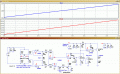
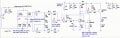
Modified for Vout = 1v to 5v
Iout = 4mA to 20mA
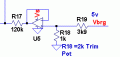
R18 is the Set 1Vout pot
Note the U5 OPA for the Vref [Offset =+1v] , uses a 6v2 Zener as voltage source.
The 2N3819 is not used [ it was for the 4mA minimum current source]
The sim used a 0mV thru 3.6mV output from the bridge.
Set R9 Gain value to give the Vout from 1v thru 5v , for your bridge output level.
E
Update:
If you are confident that the 5V for the bridge is stable, you could use that voltage in place of the 6v2 Zener diode. OK.?
hi rajit,
Modified for Vout = 1v to 5v
Iout = 4mA to 20mA
R18 is the Set 1Vout pot
Note the U5 OPA for the Vref [Offset =+1v] , uses a 6v2 Zener as voltage source.
The 2N3819 is not used [ it was for the 4mA minimum current source]
The sim used a 0mV thru 3.6mV output from the bridge.
Set R9 Gain value to give the Vout from 1v thru 5v , for your bridge output level.
E
Update:
If you are confident that the 5V for the bridge is stable, you could use that voltage in place of the 6v2 Zener diode. OK.? View attachment 156112
dear eric,
i can understand the circuit. and your last modification ie., R18 trim pot does mean for zero input adjustment (so called zero adjustment for the amplifier circuits)
what is the modification have to be done for getting 0V output for 0 input single even we add the negative supply for OPA and also +12v and -12V is enough for the circuit ?
dear eric,
sorry for the confusion.
i think i get confused at the point about zero adjustment in my circuit.
let me tell, the project ultimate need is for my input signal i have to give amplify and convert it into 4-20mA ( give to PLC)
while checking my circuit ( amplifier and v-i circuit alone) with any application (for example load cell as a source input source)
when i connect the loadcell output as an input for amplifier,
at no load condition, the load cell output is zero, so my circuit output should provide 4mA . at the time if the circuit output shows 4.3 mA instant of 4mA.
my doubt is the input zero adjustment is mean that whether adjust the trimpot R6 ( which following with jfet 2N3819) or adjust the amplifier output, to get the output 4mA.
which one should adjust?
kindly clarify it.
thanks for your support.
hi rijat,
The trim pot in the 2N3819 source sets the 'threshold' current to 4mA.
But that 4mA threshold current is only required/connected when the amplified input to the V2I, is Vinp = 0v
Normally the Vinp is from 1v thru 5v, so the Vinp of 1v creates its own 4mA threshold.
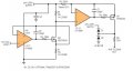
Look at this d/s for more details, it is an IC, I use.
E
Morning rajit,
Using your existing OPA's with a single power supply, achieving a Vout of zero volts is not possible,
If you add a negative voltage supply and make other modifications, Vout=0 is possible.
Let me know what you decide and we can redesign the circuit.
BTW: The fact you have built the project using general specification OPA's and components and it works as well as it does, you should feel well satisfied with its performance.

 Facebook
 Google
 GitHub
 Linkedin