How to design a multistage discrete BJT amplifier

Status
Not open for further replies.

Audioguru again

Joined Oct 21, 2019
6,826
With a 30V supply, the latest circuit produces clipping when the input is 118mV peak which is only 1.4dB more that the spec then the increase cannot be heard.
By correcting the biasing of the 2nd transistor then the clipping begins at 178mV which is an increased level of 3.5dB that is clearly noticeable (more than double the output power).

A while ago I reduced the resistance of the emitter-follower's emitter resistor so that the circuit meets spec, maybe I should have reduced it more and made enough heat to cook something.
Of course the class-A output emitter-follower is still dividing down the undistorted output level that can be fixed by making the emitter-follower operate much hotter.
 

ericgibbs

Joined Jan 29, 2010
21,477
Hi,
The TS has the assignment to design a 3 stage a transistor amplifier, to the specification as posted in post #1, so why do you insist that it has to meet your gain specification in order to be acceptable.?

I should have reduced it more and made enough heat to cook something.

And what is this supposed to mean, when the max power in a component is is approx 126mWatts.?

E
 

Audioguru again

Joined Oct 21, 2019
6,826
By reducing the resistance of the emitter resistor, I made the original design meet the spec.
By correcting the biasing of the 2nd transistor, I made the circuit work better and produce more than double the output power.
When the improvements are explained to the professor then the student is entitled to extra points.
 

ericgibbs

Joined Jan 29, 2010
21,477
When the improvements are explained to the professor then the student is entitled to extra points.
Hi agu,
But it is the student's course work assessment assignment, not yours.

So by posting your version and improvements to the TS's posted circuit, you have possibly enabled the TS to gain extra undeserved credit points for the assignment.

The rule is, we do not give Homework students direct answers to their assignments.
 

Thread Starter

GF Oberholzer

Joined May 23, 2023
39
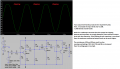
I have built the circuit according to my LTSpice simulation but I get a wave that is not correct and the frequency is also way too high. Can anyone give any advice on how to fix it?
 

Attachments

Audioguru again

Joined Oct 21, 2019
6,826
It is oscillating probably because it is built with a mess of wires on a Mickey Mouse breadboard.
The wires have inductance and the rows of contacts have capacitance changing the amplifier into an oscillator.
Electronic circuits that have gain must be built neat and tidy. The output must be kept away from the input.

I build prototype circuits compactly soldered on stripboard. I plan the parts layout and cut the strips of copper to short lengths so that they are the wiring of a pcb. Only a few very short wires are the remainder of the wiring. Most of my stripboard prototypes were sold as the final product but a few were given to a pcb manufacturing company.
 

ericgibbs

Joined Jan 29, 2010
21,477
Hi GF,
Please post values for the Input frequency & amplitude.
Also, the amplitude of the Vout signal.

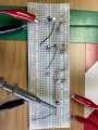
A photo-shot of the amplifier layout would help.

Ignore the Mickey Mouse comments, most of us are here to help guide you with the project, not to make you look stupid.

A simple 3 stage transistor can easily be built on bread board and good give results.

E

Your post #85 image looks as though you are over driving at a higher frequency than the design spec.
 
Last edited:

Audioguru again

Joined Oct 21, 2019
6,826
The scope shows 5V per division. 3 divisions is 15V p-p.
The scope's timebase is 100ns per division. 2.75 divisions is 3.637MHz.
The amplifier might be oscillating with no input signal.
 

Thread Starter

GF Oberholzer

Joined May 23, 2023
39
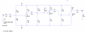
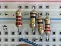
I have built the following circuit on the breadboard:
1685346431448.png
1685346490285.jpeg

The signal generator inputs a 200mV p-p signal. The DC power supply is +-15V.
It works on LTSpice but when measuring the real circuit there is only a gain of 5. What can be the problem?
 

MrAl

Joined Jun 17, 2014
13,726
I have built the following circuit on the breadboard:
View attachment 295205
View attachment 295206

The signal generator inputs a 200mV p-p signal. The DC power supply is +-15V.
It works on LTSpice but when measuring the real circuit there is only a gain of 5. What can be the problem?
Please post your .asc sim file so we can take a look.

Also check that you are really using a 200mv input and the frequency is the same (probably use 1kHz).
 

ericgibbs

Joined Jan 29, 2010
21,477
Hi GF.
I assume the gain of 5 is within the defined bandwidth.

The gain of your 2N2222a could be in the order of BF=100.

Try your LTS simulation with a BF=100.
E


BTW: Your layout looks OK, but add some power rails decoupling capacitors 100uF and 100nF on both supply lines.

EG57_ 853.png
 

Thread Starter

GF Oberholzer

Joined May 23, 2023
39
Hi GF.
I assume the gain of 5 is within the defined bandwidth.

The gain of your 2N2222a could be in the order of BF=100.

Try your LTS simulation with a BF=100.
E


BTW: Your layout looks OK, but add some power rails decoupling capacitors 100uF and 100nF on both supply lines.

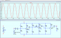
View attachment 295208
When changing BF to 100
Hi GF,
Tried with a 2N2222 BF=100 no apparent change in overall Gain=50
EView attachment 295210
Yes I saw the same.
 

ericgibbs

Joined Jan 29, 2010
21,477
Hi GF.
Could you please confirm how the +V and -V and 0v/Gnd are connected on the bread board.?
E


Added: Check that the 1st stage gives a Gain =10, with a 200mVppk 1kHz sine input
 

Thread Starter

GF Oberholzer

Joined May 23, 2023
39
When I calculated the resistor values for a gain of 10 on the first stage I used a 10k load. I switched the 10k with a 2.2k and calculated new resistor values for 10 gain and it worked.
 
Status
Not open for further replies.
Top