Facebook
 Google
 GitHub
 Linkedin
Thanks for the explanation. Just to clarify, I need to measure my low and high cut-off frequencies at 3dB?Hi GF,
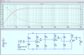
Change the .tran to this image, add the 1V AC to the V1 source details.
Add a Node label as Vin and one for Vout, using the F4 key.
Ask if you have a problem.
E
View attachment 294977View attachment 294979View attachment 294980
How to design a multistage discrete BJT amplifier
- Thread starter GF Oberholzer
- Start date