How to Create a 12V Breathing/Fading LED Circuit with My Current Components?

Thread Starter

StrayDoggo

Joined Oct 25, 2024
6
Hi everyone,

I'm working on a project to make an LED that fades in and out (breathing effect) and operates on a 12V power source. I have the following components:
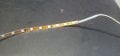
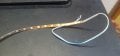
12v strip led
3x 3.7v batteries connected in series = 12v (with added extra voltage when fully charged resulting in 12v)


BC547 NPN Transistor
NE555 Timer
C817 Optocoupler
330uF 50V Capacitor
330uF 25V Capacitor
1000uF 25V Capacitor
1000uF 50V Capacitor
100k Potentiometer
15K Ohm 1/4W Resistor
10K Ohm 2W Resistor
100K Ohm 1/4W Resistor
1K Ohm 1W Resistor
4.7K Ohm 1/4W Resistor


Could someone guide me on how to wire these components to achieve the breathing effect? If any additional components or specific values are needed, I'd love some advice. I’d also appreciate any example circuits or explanations on how to calculate the timing for smooth fading.

Thanks in advance for any help!

I am not very good with circuit diagrams I am a visual learner, I also checked youtube but it didn't help me much and it was over complicated.
 

Attachments

BobTPH

Joined Jun 5, 2013
11,463
How many LEDs are in series on your strip? Likely three if blue as in the photos. If you look at the strip, it should be the number between cut points that are marked on it.

If that is the case, it will likely be completely out at around 7-8V. It would help if you could verify that voltage.

Then you need a circuit that will vary the voltage from the “off” voltage to 12 and back down, i.e a triangle wave. The 555 can give you a sort of triangle from 4 to 8V.

Just thinking out loud through my keyboard here.

How many LEDs in the strip? Needing what current? A single BC547 probably cannot carry all the current for more than 10 groups of 3.

You could apply that voltage through a suitable resistor to the base of the BC547 used as a low side switch.

You might get something okay from that.

If you have more than 1 BC547, using a darlington might be helpful, though it would eat up more voltage than a single transistor.

If you only have one of each component, you are likely to kill the BC547 during experimentation.

Start by making an astable from the NE555 at the desired frequency.
 

Thread Starter

StrayDoggo

Joined Oct 25, 2024
6
I’m sorry if I didn’t understand what you were asking. I’m not an advanced expert when it comes to electronics, but I know quite a few basic things.

So let me tell you what I know about the leds. It's a very cheap 12v led. It's sold as a 3 feet long piece and even if you cut it in half or more or less it still lights up. I had to cut mine a few inches for my project it but I used most of it, and it only lights up when applied 12 volts. Either from a battery or power supply. It only works with 12v power and consumed about 300mah.

let me show you a picture of the led strip.

I hope this helps. There is only one strip led I am using. How many small smd leds in that strip, I don't know nor I think it matters, all I know it must require 12 volts to light up.
 

Attachments

ElectricSpidey

Joined Dec 2, 2017
3,312
That transistor will not cut it driving that load.

If you can get an NPN power Darlington and at least 2 1k resistors you could make a pretty decent breathing project.

Set up the 555 in astable mode...you can find that online.

Set up the Darlington in follower mode. (the load on the emitter)

Connect the base of the transistor to the positive connection of the 555s timing capacitor.

Connect the output of the 555 to the control voltage pin using a 1k resister.

I'm sorry, I can't make a schematic I don't have access to my other comp right now.
 

BobTPH

Joined Jun 5, 2013
11,463
Yes, those are 3 in series as I guessed. Other strips I have seen explicitly mark where you can cut it. This one can only be cut just before the black components, which are resistors for the next three LEDs. If cut anywhere else, the last ine ir two will not light, but no harm is done.

It will light up, but more dimly, for some volts below 12V. If you have a variable voltage power supply you could determine that.
That transistor will not cut it driving that load.

If you can get an NPN power Darlington and at least 2 1k resistors you could make a pretty decent breathing project.

Set up the 555 in astable mode...you can find that online.

Set up the Darlington in follower mode. (the load on the emitter)

Connect the base of the transistor to the positive connection of the 555s timing capacitor.

Connect the output of the 555 to the control voltage pin using a 1k resister.

I'm sorry, I can't make a schematic I don't have access to my other comp right now.
That will not work. The max range of the timing capacitor at 12V is 4 to 8V. A darlington will dropp another 1.2V from that, si 2.8 to 6.8V. It is not likely to light uo at that.

I just looked up the BC547, it can only handle 100mA. So at 20mA each, that would be only 5 strings of three or 15 LEDs.
 

Thread Starter

StrayDoggo

Joined Oct 25, 2024
6
Hey I have a request to everyone replying to this. I really suck at understanding basic schematics and things like the ground and negative pin and such parts. I can navigate things with clear direction and once I have identified the parts.

So please me more detailed but simple and Perhaps use basic images like this. I understand things better this way. Sorry about this.
1729864658897.png
 

Thread Starter

StrayDoggo

Joined Oct 25, 2024
6
so
Yes, those are 3 in series as I guessed. Other strips I have seen explicitly mark where you can cut it. This one can only be cut just before the black components, which are resistors for the next three LEDs. If cut anywhere else, the last ine ir two will not light, but no harm is done.

It will light up, but more dimly, for some volts below 12V. If you have a variable voltage power supply you could determine that.

That will not work. The max range of the timing capacitor at 12V is 4 to 8V. A darlington will dropp another 1.2V from that, si 2.8 to 6.8V. It is not likely to light uo at that.

I just looked up the BC547, it can only handle 100mA. So at 20mA each, that would be only 5 strings of three or 15 LEDs.
what should I do?
 

BobTPH

Joined Jun 5, 2013
11,463
You are right, with your modification you get ~11V at the top minus 1.2V for the two diode drops giving you roughly 9.8V at the strip. Might work, but nowhere near full brightness with 12V power. But 3 Li Ion batteries will give you 11.1V for most of their life, so more like 8. 8V at the strip. I expect that would be very dim if it lights at all.
 

Sensacell

Joined Jun 19, 2012
3,767
Did you get that parts list from ChatGPT?
I think you are operating under some unreasonable expectations here.

Smooth fading with those LED strips ain't gonna work with a simplistic analog scheme.

PWM is the way to go- the simplest dual 555 timer circuit, one timer generates the PWM while the other creates a ramp to control the PWM. (still not simple)

Much simpler- use a microcontroller, it could be done with 4 parts

(1) Microcontroller

(2) Mosfet

(3) voltage regulator

(4) capacitor
 

Thread Starter

StrayDoggo

Joined Oct 25, 2024
6
Did you get that parts list from ChatGPT?
I think you are operating under some unreasonable expectations here.

Smooth fading with those LED strips ain't gonna work with a simplistic analog scheme.

PWM is the way to go- the simplest dual 555 timer circuit, one timer generates the PWM while the other creates a ramp to control the PWM. (still not simple)

Much simpler- use a microcontroller, it could be done with 4 parts

(1) Microcontroller

(2) Mosfet

(3) voltage regulator

(4) capacitor
Oh no. I got the list from random youtube videos. ChatGPT was even more complicated. I don't know how to do it. It can't be this complicated right?
 
Top