I had noticed a small offset in the In-Amp output with only single input pin connected to GND. I will try connecting both input pins to GND through 100k resistors. I expect this will eliminate offset error completely.
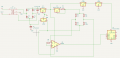
This is a amplifier circuit for Wheatstone bridge output. Bridge is excited by constant current.
Is it OK to take GND from centre tap of transformer? Whether this will results in noise in In-Amp or ADC outputs?
(For simplicity, I have not shown filter caps and other safety components in the schematic)
For this circuit to perform in a reasonable manner it is required that the center tap of the TRANSFORMER BE TIED TO THE CIRCUIT COMMON, WHICH MAY ALSO BE GROUND.
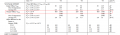
Oh. I missed to mention the units. All values are in millivolt. All AD620 indicated values are 1.34 mV higher than indicated in millivolt source.
Please note that AD620 amplified the millivolt signal [Gain=50.4] and its output is fed to ADS1115. What I have indicated is the measurement of ADS1115 which is operated with unity gain [So measurement= COUNTS X LSB ÷ AD620GAIN]
Yes I purposefully dropped them. This was the first circuit I made by myself (even I soldered first time) so the confidence level that this circuit works was too low so I neglected those caps. As I used switching supplies for ad620, wiring is messy, filter caps are absent, Gaussian noise at output was high. I managed it through averaging at microcontroller level. Presently I am planning to improve the circuit.
But I presumes filtering has no relation with offset error.
Hi, aoo,
Without good decoupling at these low signal levels will get you problems.
For the mVout offset problem, disconnect R7 from pin #4 of U2 and connect it to 0v/gnd.
Measure Vout again, and post the result for 0mV input to the AD620
E
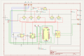
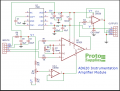
I got a schematic of a readymade AD620 module available for purchase. Whether this circuit works if S+ & s- is connected to a standalone millivolt source. I think this circuit also face same issue related to input bias currents.

 Facebook
 Google
 GitHub
 Linkedin