How Do You Choose a Gate Resistor for a MOSFET-Based PWM Circuit?

Thread Starter

cedricuk

Joined Sep 7, 2026
32
I'm interested in understanding how to choose a suitable gate resistor when using a logic-level MOSFET to switch a load with PWM.

The resistor limits the peak current from the driving pin, but it also affects switching speed. How do you balance these factors when selecting a starting value?

Does the choice depend mainly on the MOSFET's gate charge, PWM frequency, and the capabilities of the controller's output pin? I'd be interested in hearing how experienced electronics hobbyists approach this in practice.
 

MrChips

Joined Oct 2, 2009
35,299
I would do the similar analysis that you would do for calculating a pull-up resistor.
Because the input gate current of a MOSFET is very low, technically, you don't need a gate resistor.

In the absence of proper driver sink capability, you might need a gate pull-down resistor. Then you would add a gate drive resistor to limit the drive current.

Once you start adding resistors, the gate capacitance must be taken into consideration if switching time is of concern.
I cannot make recommendations until you know the PWM frequency and switching limitations as well as the capacitance at the gate node.

For most hobby applications, I would assume that the PWM frequency is low and hence switching time is not a problem.
 

ronsimpson

Joined Oct 7, 2019
4,884
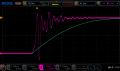
I look at possible oscillations in the MOSFET. If there is high frequency oscillations increase the resistance.
I also look at RF radiation from the supply. Same thing.
If the resistance is too high the voltage and current rise and fall time is slow and there will be power lost in the MOSFET.
There should be a point where the rise and fall time is good, but you do not see ringing.
I found this picture and added a green line. You do not want either option.
1792079756573.png
 

Thread Starter

cedricuk

Joined Sep 7, 2026
32
I would do the similar analysis that you would do for calculating a pull-up resistor.
Because the input gate current of a MOSFET is very low, technically, you don't need a gate resistor.

In the absence of proper driver sink capability, you might need a gate pull-down resistor. Then you would add a gate drive resistor to limit the drive current.

Once you start adding resistors, the gate capacitance must be taken into consideration if switching time is of concern.
I cannot make recommendations until you know the PWM frequency and switching limitations as well as the capacitance at the gate node.

For most hobby applications, I would assume that the PWM frequency is low and hence switching time is not a problem.
Thanks for the detailed explanation. That helps clarify why the gate resistor depends on the driver’s capabilities and the required switching speed, rather than being a fixed value for every circuit. I appreciate the practical advice!
 

Thread Starter

cedricuk

Joined Sep 7, 2026
32
I look at possible oscillations in the MOSFET. If there is high frequency oscillations increase the resistance.
I also look at RF radiation from the supply. Same thing.
If the resistance is too high the voltage and current rise and fall time is slow and there will be power lost in the MOSFET.
There should be a point where the rise and fall time is good, but you do not see ringing.
I found this picture and added a green line. You do not want either option.
View attachment 372286
Thanks, Ron. That’s a useful point about balancing ringing and switching losses. Too much resistance can slow the switching edges, while too little can contribute to oscillation and unwanted RF noise. I appreciate you sharing the explanation and image!
 
Top