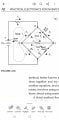
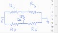
One method would be to convert R2/R3/R4 from delta to a star network. After that it's much easier to calculate voltage/current across/through R5 and R6. If you have those you can get immediately the voltage/current across/through R2, R3 and finally R4 from the original network.
He likely hasn't been exposed to Y-Δ conversions yet.
You have two unknown voltages at the T intersections. Call them Va and Vb.
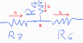
Then define your currents. I2 is not a current definition as it does not specify direction. Annotate your diagram with the quantities you will be using. The directions you assign to the currents are arbitrary -- flip a coin, if you must. But once you assign a direction, use it consistently throughout the problem.
For instance:
Now you can write each of the currents in terms of the four node voltages and apply KVL and KCL to solve for everything.
Beyond this, you need to show your best attempt to get further assistance.
I’ve always been bemused as to why Gustav Kirchhoff was credited with coming up with two “laws” which merely state the blindingly obvious. And then people invent unrealistic circuits for students to solve using his laws.
It’s just a bit of algebra. As already suggested, assume the voltages at the top and bottom of R4 are Va and Vb respectively and write down the current in each resistor according to Georg Ohm’s law. I recall that Gustav mentioned something about the sum of currents into a node are zero, but how could anyone before him think otherwise?
I'm not sure either, Jerry-Hat-Trick. I haven't figured out how to solve this problem yet, and no one has taken the time to provide a detailed, step-by-step explanation that I could learn from.
Kirchhoff’s laws, if applied directly, create a large matrix to solve. There are shortcuts. Have you learned the node voltage method and the loop current method? These reduce the number of variables and equations.
Do as Jerry has suggested. Label the voltages at R4 as Va and Vb.
Write down the equations for the currents in each resistor using Ohm's Law.
Use KCL and arrive at two equations with two unknowns. Solve for Va and Vb.
I’ve always been bemused as to why Gustav Kirchhoff was credited with coming up with two “laws” which merely state the blindingly obvious. And then people invent unrealistic circuits for students to solve using his laws.
It’s just a bit of algebra. As already suggested, assume the voltages at the top and bottom of R4 are Va and Vb respectively and write down the current in each resistor according to Georg Ohm’s law. I recall that Gustav mentioned something about the sum of currents into a node are zero, but how could anyone before him think otherwise?
Because they weren't blindingly obvious at the time. Today, we recognize KCL as simply a manifestation of the conservation of charge, but at the time, the theory of electricity was far less settled. Kirchhoff published his laws in 1845 (while a 21 year old student), based on empirical analysis of circuit behavior, as a way of extending Ohm's Law (which was met with great skepticism when it was published less than twenty years earlier) to networks of components. You might ask why it wasn't obvious by just deriving them from Maxwell's equations? Simple. Maxwell's equations weren't published for another twenty years after Kirchhoff's laws. Like Ohm, it took about a decade before the validity of Kirchhoff's Laws were widely accepted.
As for the unrealistic circuits that people invent, those are primarily as a means to get students to practice applying the concepts and working the math, while sticking to the few concepts that they have yet been exposed to. Beginning engineering students have always tended to need strengthening of their algebra skills, and that is far more the case today when so many of them have extremely weak arithmetic skills and virtually non-existent algebra skills.
I'm not sure either, Jerry-Hat-Trick. I haven't figured out how to solve this problem yet, and no one has taken the time to provide a detailed, step-by-step explanation that I could learn from.
As I stated, to get further assistance, you need to show your best attempt to work YOUR homework problem. We are not here to do you work for you. So show your work as far as you can take it. Don't worry about whether it is wrong or not. By seeing what you have done wrong, or what you have overlooked, we can help steer you onto the right path.
To be honest, I already tried solving this problem, but I think I got it completely wrong.
I’m just someone who is self-taught in electronics; my educational background is quite limited compared to university students, engineers, PhDs, or lecturers...
But you cannot use I_RbR5 and I_RcR6 to calculate I_R2 or I_R3 due to the delta-to-Y transformation.
You can do it only for the components that are "outside" the delta-to-Y transformation. Do you get it?
I meant R1, R5, and R6 only.
But since we already know V_R1, V_R5, and V_R6, we can use this to find for :
V_R2, V_R3, and V_R4
But this is not the solution you wanted.
Why did you use Kirchhoff's laws to solve for the whole circuit at once?
A quick tip:
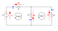
First, we label all voltages with plus and minus depending on the assumed current direction (chosen arbitrarily) and label all current directions with an arrow.
Next, identify and label all KVL loops in a circuit (two loops).
Now, when going around the loop and encountering a voltage rise (from – to +), you assign it a "+".
But when you encounter a voltage drop (from + to -) in a loop, you assign it a "-".
Or in simple words:
We add all the voltages whose arrows align with the loop direction, and subtract all those directed opposite to the loop direction.
At the end, we sum all positive and negative terms and set it equal to zero.
loop 1:
V1 − I1*R1+ I2*R2 = 0
loop 2:
− I2*R2 − I3*R3 = 0
And we're done.
Of course, the rules about which voltage we treat as positive and which as negative are arbitrary.
But if we decide to use one of them, we have to stick to it religiously.
@abcnewmember
You have created a new problem by including R1.
As it turns out, you don't need to know the battery voltage in order to determine the effective resistance.
Use the initial problem without R1 and determine the effective resistance of R2..R6. Then problem with R1 included is easy to solve.
Because of the small differences, you have to maintain at least 3 decimal places.
But you cannot use I_RbR5 and I_RcR6 to calculate I_R2 or I_R3 due to the delta-to-Y transformation.
You can do it only for the components that are "outside" the delta-to-Y transformation. Do you get it?
I meant R1, R5, and R6 only.
But since we already know V_R1, V_R5, and V_R6, we can use this to find for :
V_R2, V_R3, and V_R4
First, we label all voltages with plus and minus depending on the assumed current direction (chosen arbitrarily) and label all current directions with an arrow.
Next, identify and label all KVL loops in a circuit (two loops).
Now, when going around the loop and encountering a voltage rise (from – to +), you assign it a "+".
But when you encounter a voltage drop (from + to -) in a loop, you assign it a "-".
Or in simple words:
We add all the voltages whose arrows align with the loop direction, and subtract all those directed opposite to the loop direction.
At the end, we sum all positive and negative terms and set it equal to zero.
loop 1:
V1 − I1*R1+ I2*R2 = 0
loop 2:
− I2*R2 − I3*R3 = 0
And we're done.
Of course, the rules about which voltage we treat as positive and which as negative are arbitrary.
But if we decide to use one of them, we have to stick to it religiously.

 Facebook
 Google
 GitHub
 Linkedin


 ericgibbs