how diode works in this circuit?-Wind turbine

AnalogKid

Joined Aug 1, 2013
12,232
but there must be something which will exactly determine how much will take the battery and how much load.
Yes, the characteristics of the battery charger.

i assume, that in this scenario the 1000wh battery will be considered bigger load if it will be at 20% SOC, than 99%SOC. in the same time (20%SOC) it will be bigger load, than the 100w kanthal wire. isnt it?
Not necessarily. If the 1000 Wh battery has a 10 W charger, then it will draw at most 10 W no matter what is the battery SOC. 90 W will be available to the other loads, even if the battery is almost dead.

A battery charger is an energy *limiter*. It restricts the flow of energy down to a level that is safe for the battery. If you do not have detailed information about the charger and how it performs with various states of charge, there is no way to predict what kind of load it presents to the generator.

ak
 

Thread Starter

racmaster

Joined Feb 13, 2018
59
Yes, the characteristics of the battery charger.
charger isnt part of this situation. for better understanding i didnt place charger into question. so lets get back to the simplified schema. power goes from dc generator directly to battery and load connected in parallel. what will be the distribution of power?

as soon as voltage will be higher than battery voltage it will start charging the battery. right? until this moment all the power will be drawn by load.
 

DickCappels

Joined Aug 21, 2008
10,662
What is the output impedance and voltage of the generator and what is the condition (state of charge and internal resistance) of the battery? Maybe with this information someone can make an educated guesstimate. Unfortunately these factors and other of which I am not aware will change literally with the wind and time.

If you have a definite idea of what you want, somebody or somebodies can probably design circuitry to predictably distribute the power between battery and a dummy load while protecting the battery from overcharge.
 

Thread Starter

racmaster

Joined Feb 13, 2018
59
thats it! target is a SIMPLE controller, that will have permanently attached kanthal wire as a load, that breaks the turbine and protects it from runaway. i dont want any relays or switches here in this circuit between generator and kanthal wire load, that can fail and nothing will brake the turbine then... this controller should be as simple as possible. i want to sacrifice part of produced power to make heat instead of reaching best possible efficiency... in the same time i want small part of the produced power to be used for topping up the battery.

battery is being charged from solars, so they provide majority of its charge. wind should be only a small continuous nighttime charge, that will replace minor discharges of the battery. therefor the efficiency isnt important. its enough, if we get to 30% of produced power stored in battery, remaining 70% will be transferred to heat, so usefull anyway... not a lost power...
 

MisterBill2

Joined Jan 23, 2018
27,976
Another option that will automaticly load the generator heavily in the event of excess speed is to simple. Given that the voltage out from the generator varies with the speed, and given that this relationship is known, it can work. But it does require that there be an understanding of what speed is considered excessive.
The method is similar to the classic SHUNT voltage regulator system. IN this case, a string of diodes is used in series with the heavy load resistance, with the number of high current diodes selected so that the string will not be biased into conduction until the chosen voltage is generated. So during normal operation, charging a 12 volt battery at normal temperatures, only a very small current will flow into the braking load resistance, but when excessive speed is reached the diode string will be biased into conduction by the higher voltage, and so the additional load will draw current, requiring additional torque, and thus provide braking. No relay required, no switching devices, just diodes being biased into their conduction range. AND multiple parallel strings can be added for redundency with no additional hardware needed. At the same time, a current limiting circuit can protect the battery from excess charging current and excess charge. Those schemes are well known.
 

Thread Starter

racmaster

Joined Feb 13, 2018
59
charging a 12 volt battery at normal temperatures, only a very small current will flow into the braking load resistance, but when excessive speed is reached the diode string will be biased into conduction by the higher voltage, and so the additional load will draw current, requiring additional torque, and thus provide braking. No relay required, no switching devices, just diodes being biased into their conduction range. AND multiple parallel strings can be added for redundency
misterbill, this sounds great! can you please put down some basic diagram? also, im not fully aware, what kind of diode will act like this, as there are several types i didnt studied fully yet... i know there are some switching diodes activated by some signal, but not fully aware of that... would be very usefull if you can explain it on this diagram...
 

Thread Starter

racmaster

Joined Feb 13, 2018
59
What is the maximum current the generator is rated for?
nominal it is rated on 500w/24v, so about 22 amps. usualy it runs at about 11 amps, peaks can be up to 40amps=1000w. DC.

on AC side before rectifier i dont know exactly, but expect up to 100V, so up to 10amps. but this is something i havent prooved.
 

MisterBill2

Joined Jan 23, 2018
27,976
misterbill, this sounds great! can you please put down some basic diagram? also, im not fully aware, what kind of diode will act like this, as there are several types i didnt studied fully yet... i know there are some switching diodes activated by some signal, but not fully aware of that... would be very usefull if you can explain it on this diagram...
The circuit diagram is simple and basic: The diodes and braking load resistance are connected all in series across the generator output. The diodes are all silicon power diodes of suitable current rating to be able to handle the maximum output current of the generator. The initial guess as to how many will be required is based on the assumption of a 0.7 volt drop across each diode when current is flowing. The actual voltage will need to be measured once the actual diodes are obtained. So for this generator they will be rated for perhaps 30 amps. And if the rated voltage is 24 volts,, with battery charging voltage probably 26 volts, the number of diodes in the series string will be, (first guess), 26volts/ (0.7 volts per 1 diode), =38 diodes. (actual number 37.14). So while this method is simple it is not trivial, given that each diode will be dissipating about 30x0.7 watts of power as heat. But it will be simple and reliable in operation.
 

Thread Starter

racmaster

Joined Feb 13, 2018
59
26volts/ (0.7 volts per 1 diode), =38 diodes. (actual number 37.14). So while this method is simple it is not trivial, given that each diode will be dissipating about 30x0.7 watts of power as heat. But it will be simple and reliable in operation.
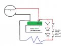
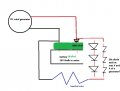
so they will act as a heating too... not bad in this scenario, pls check the first draw of the diagram, if i understand it properly. instead of 3 diodes there will be 38, just for graphical reasons there are 3.... and 2 paralel strings of 3diodes (38 in reality). so 2x3 represents 2x38 diodes.

diode wind bms kanthal 38x diodes.jpg
maybe someone can recommend some more effective diagram painting SW....
 

Attachments

MisterBill2

Joined Jan 23, 2018
27,976
The circuit in post #30 is indeed what I was describing. The resistor will reduce the amount of braking by some amount but it will also reduce the heating in the generator at the excessive speeds. No zener diodes would be part of this circuit because it utilizes the unavoidable forward voltage drop of the diodes to initiate the current flow.

Please keep in mind that at excess speed conditions the generator will be producing at or above it's maximum rated power and so there will be a lot of heat everywhere.
I still suggest a scheme to move the blades to a less efficient angle as the speed increases. There are several schemes for doing that which have been published over the years. So I suggest that additional research is also in order.
 

Thread Starter

racmaster

Joined Feb 13, 2018
59
Please keep in mind that at excess speed conditions the generator will be producing at or above it's maximum rated power and so there will be a lot of heat everywhere.
the heat is welcomed in this scenario...

however, 1 more question about the 38 diodes solution. there will be about 26v voltage drop. so if generator will be doing 28v, the kanthal wire will be only working on 2 volts? so based on ohm law it should be sized to have only about 0.01 ohm to draw about 400 wats?

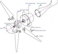
turbine has solid hub where blades are connected with screws. i cant even imagine how this could be arranged to be various by need...

2022-02-08 17.00.51 www.google.com ba22585e81ff.jpg
 

Tonyr1084

Joined Sep 24, 2015
9,744
charger isn't part of this situation. - - - power goes from dc generator directly to battery
Wait - WHAT? How are you going to charge a battery without a charging arrangement?
as soon as voltage will be higher than battery voltage it will start charging the battery. right?
In theory - yes. In practical applications you need significantly more voltage than the battery nominal voltage. In the case of an SLA battery (since I know these numbers) a 12.6V SLA will need to be charged (depending on how depleted it is) at 13.8 to 14.5V. Simply giving it 12.7V isn't going to do anything.

Now - - - - - A battery will draw some current when it is charging, whether being charged from a "Battery Charger" or from a higher voltage source. Depending on the SOC that battery is going to draw a given current for that exact SOC. But as the battery charges (SOC going up) the battery current will drop. Back when I was installing and servicing emergency lighting equipment the battery was maintained by a basic voltage regulator set to 13.8V for SLA's. That then fed the battery through a 6 volt lamp (I think. It's been many years since then). When the current was high the light would glow full brightness. As the battery charged the lamp would dim until extinguished. Thus, without a meter, looking at the lamp would tell you if the battery was drawing current. Remember this important detail: The lamp would dim as charge went up. When fully charged the lamp would go out. In short - the current draw of a battery is CONSTANTLY changing, dropping.

So if you want to know how much current will go which way you need to specify the SOC, the battery's internal resistance, available current for charging and the capacity of the battery. Then at any given moment in time you could (THEORETICALLY) describe the amount of current it will draw. But that changes moment by moment. If it's drawing 2.328A at one moment, the next moment it's drawing 2.327A. Moments later it's drawing 2.3A. As the SOC goes up the amperage falls.
 

Thread Starter

racmaster

Joined Feb 13, 2018
59
So if you want to know how much current will go which way you need to specify the SOC, the battery's internal resistance, available current for charging and the capacity of the battery. Then at any given moment in time you could (THEORETICALLY) describe the amount of current it will draw. But that changes moment by moment. If it's drawing 2.328A at one moment, the next moment it's drawing 2.327A. Moments later it's drawing 2.3A. As the SOC goes up the amperage falls.
im perfectly aware of the current going down by charging battery to 100%

is it possible to make some formula? since we are not planning a real circuit yet, lets choose a situation. choose any value of load in parallel with battery and choose any value of internal resistance, just to get to some results. afterwards we can change the values and simulate another situation. this will help me understand this case and for the future step make sizing of the planned circuit.
 

Tonyr1084

Joined Sep 24, 2015
9,744
Suppose your battery is drawing 2 amps and your load is drawing 2 amps. Suppose your source (generator) is capable of 10 amps. Each will draw 2 amps. Suppose your battery is draws 5 amps and your load draws 8 amps but your generator is only capable of 10 amps. Because there's a limited amount of current available the battery should (I said "Should") pull 3.5A and the load should draw 6.5A

Of course, when you draw MORE amperage the voltage will drop. That drop in voltage will affect the amount of current available for the whole circuit. Exactly how it will respond is math beyond my capabilities. But hopefully you understand more about how current works and its relationship to voltage and resistance. Resistance is the amount of load your "Load" puts on the system as well as the amount of resistance the battery offers to the circuit.

Now - and this is hugely important - if you're using Li-Ion or Li-Po, or any other lithium based battery you MUST include a BMS. Without it you're building a fire starter; possibly a bomb. Granted, not a big bomb, but Li's have been known to explode and/or violently erupt in flames. That's one reason why when flying on a commercial plane you're not allowed to store equipment with Ii- batteries in the cargo. They CAN bring down an airplane.
 

Thread Starter

racmaster

Joined Feb 13, 2018
59
lifepo4 technology doesnt burn or explode, in fact they are absolutely safe batteries. thanx for care, but im aware abaout batteries, having 10 years of offgrid experience with all the kinds...

lets stay by topic - paralel load and battery. the 38-diode string solution provided by misterbill brings nice workaround. no mechanical parts, just diodes. any other idea how to reach the same target?

get power distributed as good as possible to battery and load without using hi risk parts as mechanical relays....
 

Thread Starter

racmaster

Joined Feb 13, 2018
59
lipo is lithium polymer 4.2v max, lifepo4 is lithium fero phosphate 3.6v max charging. thats completly different technology.

there are videos overcharging brutally with 100c, putting in fire, axe crashing, shooting, shortcircuit....

nothing makes this battery burning.

pls, get back to topic.
 

MisterBill2

Joined Jan 23, 2018
27,976
For a solid mounted blades package such as that one there would be no blade adjustment I see. But an arrangement to torn the whole package so that the blade axis was at right angles to the wind will probably reduce the speed a lot. It would be worth investigating to see if that would be an option. And a 90 degree turn mechanism can be realized fairly simply.
As for the resistor, certainly it would need to have a lower value than the original plan. But I suggest a value that would have the whole stack, diodes plus resistor, dissipating the total power. I have not calculated the resistance for that
And still, I suggest considering a means to turn the turbine out of the wind during excess wind times.
 

Thread Starter

racmaster

Joined Feb 13, 2018
59
turning turbine is an option maybe once a year, once for 2 years when there is catastrophic wind occurs. in such a case there will be meteorology warnings and i can give the turbine simply down, which will be the only 100% safe solution...

so back to diode string solution. what happens if 1 of those 38 diodes fails? how failed diode performs, as open or closed circuit?

another question, how to cool diodes? some contact passive cooler is possible? to avoid noise from fans...
 
Top