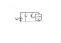
How can I make a scanner led light using 1,25 V X 0.054 ma (VIMUN SC - 3012) ?

ArakelTheDragon

Joined Nov 18, 2016
1,366
I have tried with a "standard " small led - the same situation ...
scanner led - there is no resistor
I am thinking some how the internal resistance of the multi meter is killing the toy is that possible ?
Depends on the multimeter, it can be designed to work with small currents.

What you should do is get a large value pot 100k to 1MOhm and put it instead of the load. Then check the voltage
 

Thread Starter

sciencetoolbar

Joined Apr 9, 2017
87
Depends on the multimeter, it can be designed to work with small currents.

What you should do is get a large value pot 100k to 1MOhm and put it instead of the load. Then check the voltage
The value is oscillating when I am trying to read it ( something appears on on the display but is happening so fast...and in the final I see Big zero) :)
For sure the multi meter knows to measure it
 

hexreader

Joined Apr 16, 2011
619
Won't kill anything, but maybe resistance is just enough to stop the LED lighting.

Try 10A range, just to prove leads and connection. Don't expect anything to show on meter, but LED should light as before
 

Thread Starter

sciencetoolbar

Joined Apr 9, 2017
87
Won't kill anything, but maybe resistance is just enough to stop the LED lighting.

Try 10A range, just to prove leads and connection. Don't expect anything to show on meter, but LED should light as before
I will do this ( 10 A range ) but when I wish to measure current the spheres stops spinning and the voltage and current dies with it
thx HEX
 
Last edited:

Thread Starter

sciencetoolbar

Joined Apr 9, 2017
87
Depends on the multimeter, it can be designed to work with small currents.

What you should do is get a large value pot 100k to 1MOhm and put it instead of the load. Then check the voltage
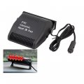
In the latest test I hacked the heating element inside the 12 V DC auto Heater 150 W (presented in the image) and I connected to the toy - I observed that the sphere spins very slowly but it spins......of course voltage died ...and the heating element was cold as ice :) - this test it wasn't made to heat the element, it was made to see the reaction of the spinning sphere at high electrical resistance 12 V DC heater.jpg
 
Last edited:

Thread Starter

sciencetoolbar

Joined Apr 9, 2017
87
In conclusion regarding the spheres stops, when I am trying to measure the current value, is not the internal resistance of the multi meter the cause ( due to the test with ceramic element ( 150 W ) , which slow the speed of the sphere with 95 % , there is have to be something else.
Agree ?
 
Last edited:

shortbus

Joined Sep 30, 2009
10,049
If you will look with attention on the open thread you will see that I answered at all the questions and I have received also some preliminary answers.
Here is a Brief :
Input : 1,25 V X 0.054 ma
Output : 2,08 V, unable to measure the current due to the sphere suddenly break

I am building an educative toy a "mechanical booster" ( keeping the same input power 67 micro-watts minus losses, increasing the voltage ) , and I requested professional help to make that led glows better. At the first look at that input, based on multiple opinions, there is no converter , joules thief ( electronic circuit ) which can help me (in this particular case, it will not start) with that mentioned input. One of the members kindly advice me for an optimization : I will replace the capacitor of the AC to DC rectifier with a smaller one, I will keep the conductors as short as possible, I will lose some weight on the rotor making small cases. Hex reader asked me about the output current. I response him there is a problem, because I can't measure it (when I connect the multi meter to measure the current the sphere suddenly stops). I am thinking the problem is the resistance of the multi meter and I asked Hex reader his opinion about this. I answered to all the questions related or not with the subject. (polite). I answered also that it can be easy replicated and I offered a link on instructables.
Now we are in this point : I am looking forward to apply on the mechanical booster the mentioned improvements offered by ArakelTheDragon + another one which I didn't see it from the beginning (loss weight). I am unable in this point to measure the output current.
After I will make the improvements I will come back with a feedback.
THX to all so far, st


Yelling at me won't change my mind, and if you claim your not why is the reply to me the only one in bold print? You and the dragon are made for each other. Just enough knowledge of things to think you talking the language, but not enough to make sense, to those your talking to that do know the language.
 

Thread Starter

sciencetoolbar

Joined Apr 9, 2017
87
Yelling at me won't change my mind, and if you claim your not why is the reply to me the only one in bold print? You and the dragon are made for each other. Just enough knowledge of things to think you talking the language, but not enough to make sense, to those your talking to that do know the language.
I don't understand why are you upset . I am sorry if I said something wrong, but you said I am not responding to the questions and I wish to demonstrate that I am responding . That why I bold the text. Sorry . If you wish to help me I will be more than glad (because this is the easiest part of my project and I really need your experience).
and I think I discovered the problem why can't I measure the current ........
 
Last edited:

Thread Starter

sciencetoolbar

Joined Apr 9, 2017
87
Because there is none?????
I have made text normal, is not bold anymore.
I don.t know yet, probably you are right it can be none I din't measure it yet, I will repeat the tests Monday in the same conditions and I will now, I am not sure I will find something (ref current) :) , but today I learned something very important :
when you use a lot of multi meters , DON' T use the same wires (test leads banana)
I will never think about this.....
In conclusion Monday I will know the current if there is any I doubt, in the mean time I will try to make some improvements.....
 

Tonyr1084

Joined Sep 24, 2015
9,744
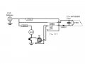
Said I wasn't going to follow this any further, but curiosity got the best of me. @sciencetoolbar - do you know what a schematic is? Do you know how to draw one? You've been asked several times and all you do is post pictures of stuff. This is not the way we analyze electronic circuits. We do it with a drawing of how each wire is connected. Here's one I did some time ago - a simple circuit, and totally unrelated to what you're doing. It's posted only for the sake of showing you what a schematic is - and what we're asking from you:
Electronic Fly Swatter.jpg
 

Thread Starter

sciencetoolbar

Joined Apr 9, 2017
87
Said I wasn't going to follow this any further, but curiosity got the best of me. @sciencetoolbar - do you know what a schematic is? Do you know how to draw one? You've been asked several times and all you do is post pictures of stuff. This is not the way we analyze electronic circuits. We do it with a drawing of how each wire is connected. Here's one I did some time ago - a simple circuit, and totally unrelated to what you're doing. It's posted only for the sake of showing you what a schematic is - and what we're asking from you:
View attachment 164365
Tony did I said something wrong to you ? I saw you left.......after I send you some locations for the holiday.
welcome back
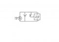
low motor consumtion circuit :
sphere motor circuit.jpg
 
Last edited:

Tonyr1084

Joined Sep 24, 2015
9,744
Whats the diagram for the circuit board?

And no - you didn't offend me, I got tired of asking questions that were unanswered. OK, you showed me a vacation spot. That spot didn't correlate with what you said about being in Ruanda. When questions are asked and non-answers are given, we, that is "I, me personally" suspect that maybe we're not being dealt with on a completely honest level. Rather than continue to ask I just accept that I'm not going to get the answer I need.

I see you do know how to make and post schematics. However, the board is - at this point - a complete mystery. Exactly what is on the board? Components? Values? If there's an IC or two (or more) what do they do? Not getting satisfying answers leads us (me) to become suspicious.

So no, you didn't offend me. No more than when someone asks a question and doesn't get an answer - or worse, gets a non-answer. What's the difference between no answer and a "NON" answer? A "NON" answer is an answer that answers nothing. If I were to ask "What time is it there?" and you reply "Yes, the clock is displaying the time satisfactorily." THAT is a non-answer. Not what was asked. So showing me vacation resorts does not answer "Where was the video shot from?"

If you ask "Where do you live" and I said "Salt Lake City, Utah" THAT is an answer. If I say I live in the ninth house from the corner of my street - that doesn't answer the question.

No, I'm not angry. I don't get angry or sweat the small stuff. I also don't sit and bang my head against a stone wall because it feels so good when the pain stops.
 

LesJones

Joined Jan 8, 2017
4,524
Hi sciencetoolbar,
In post #33 I was expecting you to have connected the meter across the supply but from you picture you do have it connected in series which is correct. The symptoms fitted with it being connected across the supply. I have seen quite a few beginers on the forum connecting the meter across the supply when trying to measure current. I don't understand why it should prevent the LED from lighting when connected in series with it.

Les.
 

ebeowulf17

Joined Aug 12, 2014
3,307
If you will look with attention on the open thread you will see that I answered at all the questions and I have received also some preliminary answers.
However, the board is - at this point - a complete mystery. Exactly what is on the board? Components? Values? If there's an IC or two (or more) what do they do?
I'm with Tony on this one. The most important question we need answered in order to help with any electronics issue is:

"Can we see your *complete* schematic?"

We need to know what's in the mystery box. We need to know what components are on that PCB and how they're connected together. Otherwise, we can't understand what your circuit is supposed to be doing, much less help you optimize it.
 

BobTPH

Joined Jun 5, 2013
11,618
On the 10 A range, the resistance will be well under 1 Ohm. At 54uA of current that would be dropping less that 54uV from the 2-3V needed to light the LED. No way it causing your motor-generator to stop or even having a visible effect on the light coming out of the LED.

So either you are doing something wrong, or you are trolling us.

Bob
 

hexreader

Joined Apr 16, 2011
619
Now that I am in helpful mood, I will clarify on behalf of OP...

I think the OP already worked out that the multi-meter test leads were no good. Hopefully we will find out current to scanner LED soon.

The mysterious circuit board will remain a mystery, as is was scavenged from a flying toy. It seems to be some kind of oscillator/switcher device that works on low voltage. A black blob hides the workings. As the OP seems to have no scope (maybe he does?), we might never know what waveform or frequency it gives out.

The rest of the circuit is simply an elaborate step-up transformer (let's just ignore the spinning magnet), rectifier and LED (no resistor).

Presumably power output will always be so low that LED does not burn out, despite a lack of current limiting resistor.
 
Last edited:

ebeowulf17

Joined Aug 12, 2014
3,307
As for amp measurements killing the circuit function, is it possible the fuse on the meter is blown?

It's a pretty common problem because it's so easy to make the connections incorrectly for current measurement, and it only takes a split second to blow the fuse if you get it wrong.

A blown fuse would explain why it kills the circuit completely. So, we should rule out that possibility before going any farther. Are you able to measure current through other circuits with the same meter? If you haven't already tried it, you could measure current through that 12V heater you used in another test, just to confirm that your meter's current measurement functions are working and that the fuse isn't blown.

The other thing you could do is put a small resistor, anywhere from 1-100ohm, in place of the meter and then measure voltage across it to calculate current. Lower resistance will impact circuit function less, but mean smaller voltages that might be too small to measure. Higher resistance means easier voltage measurements, but greater impact on circuit behavior.
 

LesJones

Joined Jan 8, 2017
4,524
Open circuit meter leads or a blown current range fuse in the meter would explain the LED not lighting but I don't see how it can stop the magnet ball thing from rotating. (This is why I suspected that the TS had connected the meter incorrectly thus shorting out the output.) It has occured to me that if the drive coil and the generator coil were placed close together (Possibly both on the same laminated feromagnetic core.) to form a crude transformer the power transfer would be more efficient than via the spinning magnet ball thing.

Les.
 

Thread Starter

sciencetoolbar

Joined Apr 9, 2017
87
Now that I am in helpful mood, I will clarify on behalf of OP...

I think the OP already worked out that the multi-meter test leads were no good. Hopefully we will find out current to scanner LED soon.

The mysterious circuit board will remain a mystery, as is was scavenged from a flying toy. It seems to be some kind of oscillator/switcher device that works on low voltage. A black blob hides the workings. As the OP seems to have no scope (maybe he does?), we might never know what waveform or frequency it gives out.

The rest of the circuit is simply an elaborate step-up transformer (let's just ignore the spinning magnet), rectifier and LED (no resistor).

Presumably power output will always be so low that LED does not burn out, despite a lack of current limiting resistor.
There is no mistery - Motor circuit details :
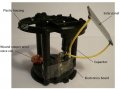
There are a total of four electrical components. A small solar panel ( VIMUN SC-3012-2A, 29.44mm×11.6mm×1.1mm, 4 cells. The following specifications were listed, 2.0 Vos, 9.0 UAsc, 1.5 Vop, at 200Lux), a 470 uF 10 V electrolytic capacitor, a coil iron less with thin copper wire and a small circuit board with a black blob on it.

Under this blob is the integrated circuit chip. It provides the correctly timed pulses to the coil and magnet combination. The integrated circuit is more or less just a low frequency oscillator which runs at approximately 1 Hz most likely driving an open drain NMOS switch ( output on pin 3 ) which periodically connects the coil to the - terminal. The circuit pulses the 18 mH coil causing the neodymium sphere magnet spinning.
 

Attachments

Last edited:
Top