Thank you for your circuit. Any circuits are of help. AVR failures seem to be a common problem and as I've mentioned the DLR control on my Buick and Olds were similar failures. I believe mostly because these devices are minimal engineered. If I'm successful with replacing the BU931T it will be external to the AVR itself on a substantial heatsink. Further this failed AVR had no heat sink compound appllied either. Small wonder they fail so quickly. I'm sure your circuit can be adapted to other machines with minor changes to allow for different stator and exciter winding voltages. Some bench tests, injecting voltage and current into the field winding under varing loads should point one in the right direction. Could be a lot cheaper than OEM parts, IF they are available.
Thanks again. Your drawing is filed under Generators.
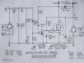
If the Generator failure mode was no output (0V rms) then the shorted diode is likely D7 (1N4006) otherwise its likely D6 (1N4006), if it failed with max output (142Vrms). How did it fail? My schematic has an error... D6 and D7 should be swapped.
LTspice doesn't do PCB layout. There are free layout tools online... google: PCB layout.
I got my gen to run today. Lots of air is drawn in around the PCB and seems to exit at the other end of the gen near the engine... this is good.
The BU93T (Q3) is a tuff transistor and is designed to run hot and to work in this kind of application. I'am anguish to here if it tests okay. It is a darlington (b-e resistors built-in) so it may not test with a simple meter. You can use a 9V batt in series with a resistor (lamp?) across the emitter-collector, then drive the base-emitter with a 5K res from +9V to base... lamp should turn on.
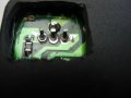
Do all the generators have burned PCBs? Could the heat have caused Q3's pin soldering to melt and open?
Jumped into this thread couple days ago. Good one. Very helpful.
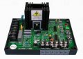
Anyway the Coleman Powermate I aquired recently has regulator problems. In mine I found a shorted BU931T which I ordered and installed tonight. It fixed the problem. I pulled most of the epoxy resin from the regulator and your schematic is spot on. I intend to mount the BU931T on a separate large aluminum sheet inside the end bell and run wires to the board, using silicone and resin to seal and stabilize the parts. A second problem not related in this machine is the low oil sensor. It times out and shuts down the generator so that needs replacing as well. All in all it will still be a low cost unit. When done I'll post pictures of the changes.
Thanks guys for all the information and drawings. Very interesting forum and very helpful.
Here is the completed repair and modification to the regulator on the Coleman Powermate Model PC473503. The BI931T was fried but the rest of the circuit was fine.
Try this: All the Home Depot stores that have a Tool Rental department have Honda Generators. Get in good with the Master Tool Tech and he should be able to order you one. They have all the service manuals as well. If memory serves me, the price is about $40.00
Good luck!!
Don
I just ran across another Coleman with fried AVR. This was probably due to shorted windings which I have replaced. Now waiting for more BU931T Darlington transistors on back order (20). There was more damage to this regulator this time but nothing that can't be corrected. Just a few blown traces and some diodes.
I ran the engine without a regulator just to check the winding repairs and it's putting out 150 volts no load. I did have to flash the fields to get it to produce voltage. Just hit the brushes with 12 volts DC from a car battery, (observing polarity). Instructions in the owners manual.
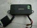
Follow up on the last generator repairs. All done and working fine. From my limited experience, the replacement regulators for these generators is on a board mounted over the brush holders. The older style regulators are in a black plastic case mounted on the side. Circuits are essentially the same. Only minor additions like varistors in the newer one. If anyone finds one of these style generators with no voltage output I'd first try a new Darlington. Just cut the leads to the transistor, solder on some wires to a separately mounted heat sink and BU931T. Quick and easy and chances are it will solve the problem. Cost: about $2.50.
Hello my english is bad and sorry for mistake. I need AVR for 3faze generator with rotor resistance is 4om mesured on brushes). Generator is aprox 6kw 3000min-1. Can I use shematic from picture above. Any one help is welcome. Thanks
Any reason not to add the counter-EMF diode directly to the rotating part (the rotor), of course observing polarity? It would save the collapsing EMF voltage spike from traveling through the brushes. Some kind of physical security (maybe epoxy) might be desirable here, too. That doesn't preclude adding a second diode on the other (non-rotating) side of the brushes, in parallel.
Also, the universal AVRs are getting REALLY cheap on Flea-bay, which might make this repair process kinda' senseless unless you can identify faulty parts quickly.
Yes I do repair them, just re solder & fill the hole with Hot Glue. They are realy hardly worth repairing a they are quite cheep on Ebay. But they usualy want the generator going ASAP as they are a primary powersuply in remote areas & run long hours. The part doesnt get hot but is subject to a lot of viabration.
So, if I were going to solder (add) a counter-EMF diode across the field winding, (primarily to reduce brush arc, but also to protect possible inadequate PIV ratings on the field rectifiers), would it be better to add it on the winding side of the brushes (having it also rotate), or in the bell end (possibly directly across the brushes)?
Or, maybe add two diodes, one in each place?
How warm would one expect these to get?
You think a 6-amp, 1000-volt PIV diode would hack the mission?
In most things, I prefer "over-kill", just to be SURE! I've already added thermal grease to the two stud-mounted rectifier diodes.
This particular Coleman gen-set has no AVR at all (just two diodes and an electrolytic to produce field current), but this is the most appropriate thread I could find in which to post.
Brush noise is broad spectrum and very high frequency so a diode will have little, or no effect. Use a good quality noise suppression capacitor (0.1uf) at the device you want to protect, not at the noise source.
A diode is still effective for reducing the back emf from the winding inductance. Place it near the device being protected.
My purpose for the diodes is not to reduce EMI (or RFI, if you will), but to reduce arcing and thus reduce the erosion of the slip rings (or disks, in my case).
What is the feasibility of adding an external AVR to this, a Coleman Powermate 5KW unit.
Hello
I miss the electronic diagram of a Automatic Voltage Regulator AVR 0-110 V
it is used to excite the rotor generators
Is what you can help me please
hi,
I'm doing a similar project.. i have to design an AVR for a single phase alternator(220v, <10 KVA).The existing AVRs have a feature of underfrequency shut down... i.e. below a specified frequency, which can be adjusted by a potentiometer...
Kindly suggest me a frequecy to voltage converter IC which is low in cost..
Hello
I miss the electronic diagram of a Automatic Voltage Regulator AVR 0-110 V
it is used to excite the rotor generators
Is what you can help me please
Hello
I miss the electronic diagram of a Automatic Voltage Regulator AVR 0-110 V
it is used to excite the rotor generators sadekmar86@yahoo.fr
Is what you can help me please
 Facebook
 Google
 GitHub
 Linkedin
 290.3 KB Views: 1,119
")