Help with Horizon Quantum II HRC Treadmill

Thread Starter

sharpharp

Joined Feb 14, 2015
10
Hi all,

Great forum, joined to say Hi but been visiting a while.
Wondering if anyone can help with an issue with my Treadmill.

I have a Horizon Quantum II HRC Treadmill which has the following fault:
When pressing the START button, the motor and belt runs at full speed. The LED speed shows the default 0.5mph, but as I said the actual speed in FULL speed.
If I adjust the speed using the speed buttons, the LED shows the increase/decrease in speed but it has not affect on the actual belt and motor which are running at FULL SPEED.

The incline buttons work fine, and also the STOP and START buttons.

So issue is, soon as START is pressed, it runs at Full speed.

I'm no good with electronics (when it comes to circuit boards) but always willing to have a go.

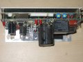
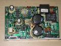
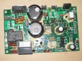
I've taken the MCB (Motor Control Board out) which is part number 013675-EH (according to Horizon support). But the price of a new board is more than £190+

I've done a visual check of the board and there doesn't appear to be any burnt components, but other than that I haven't a clue.

Could anyone be so kind as to help me diagnose the issue?

Many thanks,
Sharpy
 

Thread Starter

sharpharp

Joined Feb 14, 2015
10
Hi Max,

Thanks for your reply, but I am not electronically minded, so didn;t understand a single thing you said.
Any chance of that in laymans terms?
 

MaxHeadRoom

Joined Jul 18, 2013
28,681
The controller usually uses a tachometer on the back of the motor to control and monitor the rpm, this is commonly in the form of a slotted steel disc on the rear of the motor.
It uses an optical sensor/interupter type of device to detect the rate slots as they turn past the sensor.
If this is shot, then the board thinks the motor is not turning and it needs to ever increase the speed.
Max.
 

Thread Starter

sharpharp

Joined Feb 14, 2015
10
Thanks for the explanation.

Not even looked at the motor, as I assumed the Motor Control Board was the culprit.
I'll have a look at the Motor to see if I can see this slotted steel disc you mention and report back tomorrow.

Appreciate the help,
Sharpy
 

Thread Starter

sharpharp

Joined Feb 14, 2015
10
Hi max,

Can't see any steel discs. I've uploaded pics of the motor. There are two plastic slots (one on front and one back of the motor - see pics) but can't see any steel discs.

There is a speed sensor on the side of the treadmill near the belt is that the other place it could be if not on the back?
 

Attachments

MaxHeadRoom

Joined Jul 18, 2013
28,681
It could be located on another point, the motor is the common one, also if internal to the motor, there is usually more than two wires entering the motor.
Can you post the belt sensor.
Max.
 

MaxHeadRoom

Joined Jul 18, 2013
28,681
That shows a reed switch and magnet operator, reed switches, being mechanical are prone to a short life, it should be easy to test by unplugging and place a ohm meter across the contacts and use a magnet to see if it opens/closes.
Max.
 

Thread Starter

sharpharp

Joined Feb 14, 2015
10
Hi Max,

I've been out to test the Sensor as you mentioned. With a Voltmeter set it to ohms, tested it without being near a magnet and it displays nothing. Soon as I put it near the wheel (where there is a magnet) the reading went to 01.0 ohms. So it seems the sensor is ok.

What now?
 

MaxHeadRoom

Joined Jul 18, 2013
28,681
Other than that next it could be the motor controller FET's or SCR's, dependant on how it is controlled, it would really need a board schematic to take it much further.
Can you post a Pic of the main board?
Max.
 

Thread Starter

sharpharp

Joined Feb 14, 2015
10
Hi,

MCB pics included: This is a double board, the top board plugs into a secondary board as you can see from the pics:

I've looked everywhere on the internet for the schematics for the board but cannot locate them. What I can tell is that the following info is printed on the board:
JHT.co
2003.04.02
PCB230D002F
220V
2.0 HP

If you need a pic of the under-board, let me know.

Again, cheers for the guidance so far...
 

Attachments

Thread Starter

sharpharp

Joined Feb 14, 2015
10
Unscrewed the top board. There are 4 components screwed to the heatsink:

from left to right they are marked as follows:

1. IRFP360 ir503L 8A
2. MOSPEC U15 A60
3. S6025L A5
4. Sun-B MP35108

Two more pics, top board and bottom board
 

Attachments

MaxHeadRoom

Joined Jul 18, 2013
28,681
You should check them all for any kind of short circuit or very low resistance, measured in both directions, problem is they are best checked out of circuit.
Max.
 
Top