Need Help! Motors stopped working on Horizon T900 treadmill

Thread Starter

Joshua Mazurek

Joined Oct 24, 2017
4
Hi everyone.

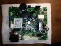
The motor control board talked about below is Johnson Fitness JDYF02L RevG. The treadmill is a Horizon T900.

I now have two problems. The second problem was accidentally created while trying to debug the first problem.

The first problem is the incline feature doesn't work on the treadmill. The treadmill was purchased like this in hopes that I could get the incline feature working. The motor for the incline works (it's an AC motor) as I just hot wired the motors connectors from an extension cord *carefully* and i can make the incline go up and down.

The second problem is that now the other motor (the traction drive motor which turns the walking belt) doesn't work either. This problem I DID create accidentally while probing around on the motor control board. I was on the long white connector measuring voltages when the probe slipped and shorted the neighboring pin. Can't remember exactly but I either shorted pins 6/7, 7/8, 8/9, or 9/10. I am calling pin 1 the first pin on the left of the long white connector on bottom in the attached picture. (Thanks to Silmarillion for supplying the picture as I don't have the board on me right now) As soon as I shorted it, the traction motor stopped turning and does not respond to commands from the panel. I would need to confirm but I am pretty sure the relays still click on when the Start button is pressed which gives me hope.

There is a wealth of knowledge regarding these boards here and I am hoping this post finds IamJatinah who appears to have a deep working knowledge of these boards.

Does anyone know how to tag another member or IM them?

If you have any experience with these boards or ideas of what I might have done any comments are appreciated! Please ask questions. I am desperate.
Thanks to all
-josh
 

Attachments

IamJatinah

Joined Oct 22, 2014
136
Hi Josh, Sorry to hear of your troubles ;o( The "fat-probing" happens to us all, trust me!
OK, not all is lost of you didn't hear a large snap and sparks, as usually this controller will let go rather ugly when it flips out.

I commend you on testing the lift motor, and I hope we measured the 3 bigger leads with a meter to see the two separate windings inside this lift motor, one for each direction of the travel(screw throw).(White-Red=down, White-Black=up)

Please do be careful to never pinch a lift motor as they are not build that well and usually get damaged during pinches, this being the reason for "limit switches" in many treadmill designs to avoid this possibility. Horizon used to have dual-internal cogs that would open limit switched in each direction to avoid pinches, but not sure if that is still the case.

So, the original issue was no lift operation then we fat-probed and killed motor drive. Ok....lets work backwards.....

Lift can only work if/when that walking belt is active, under a users command, but can reset on it's own after a workout....
1). You tested the lift with success, we can take that out of the equation, nice work!
2). There are relay drive circuits on the lower board that are "Exclusive"- meaning only one direction allowed at any one time.
a) This Exclusive relay drive is made up of SMT transistors, a pair for each relay, and supporting parts
b) The lift relay drive signals come from the upper board as TTL-level "active high" for Down or Up
c) A failure in the lift relay drive circuit could hold both directions from working
3). A logic failure on either the upper output drive circuit, or the lower input I/O circuits can affect the other mated interface

4). The motor drive failure could be troublesome if we took out the PIC chip. If we snapped the PIC chip, that board is finished unless you had another scrap board to pull a known good programmed PIC from and plant it onto the suspect board. This PIC does run on +5v so voltages of 6v or higher on the wrong pin can kill things. Just as sensitive, is the input waveshaping IC you see on the board near that longer white connector. Be Aware.....replacing surface mount parts is something that takes training and practice, one shouldn't try this as a hobby, as I can nearly promise burns and issue's. Both of these parts are SMT parts and are difficult to replace unless you have a nice hot-air set-up or are versed in SMT rework.

5). Check D14 for shorts, if shorted, then our +5v logic power rail has been hit with excessive voltage, this usually shorts D14 but some production runs omitted this zener.

In this case, it might be easier to zip you a known good lower to try in the system? There are no schematics for this other than in my head, and the board also has 3 separate ground rails on it that makes troubleshooting troublesome for those unaware of this.

I would check all the diodes around the PIC chip and near the white connectors, along with D14. Many of the glass diodes are MELF style and are round and sit on the pads during production, so you must be careful when measuring them.

Anyhow....hope this helps.... and you can drop an email to jatinahATrocketmailDOTcom if needed.
 

Thread Starter

Joshua Mazurek

Joined Oct 24, 2017
4
First off let me preface by saying thank you! And also, I am away on business and have 2 children under 3, and a rather chronically sick wife so my "free-time" is extremely limited but I should be able to plug this board back up this weekend sometime and check things out if needed.

....(White-Red=down, White-Black=up)

Please do be careful to never pinch a lift motor
I dont remember the exact wiring but I was ale to make the lift motor go up and down using a cut off ac cord. When you say dont pinch, you mean dont continue to feed the motor power once it has reached its limits (whether up or down)?

Regarding 2) and 3), I understand what you are saying but I dont really know how to test what is faulty.
  • Are the transistors the little SOT23 guys next to the 2 identical relays on the south west corner of the picture I originally attached?
  • Should I solder some leads on the board and then measure voltages or something?
  • Maybe check to see if the incline up/down buttons registers a TTL on the control board? I dont want to cross grounds so I would need to find the logic ground first....
Regarding 4) and a fried PIC. Do you know if write protection was enabled when programming this chip? I have a MPLABs ICD at work that has been sitting in a box that might be able to pull a hex file provided the write protection wasn't enabled (long shot, I know). I am quite comfortable reworking SMT parts and have designed/worked with TSSOP and QFP parts so a SOIC component should not be an issue to replace. I have access to a quality hot air rework station etc. Solder wick is your friend for sure!

Regarding 5). I will check the zener at D14 this weekend.

In this case, it might be easier to zip you a known good lower to try in the system?
I dont really understand what you are saying here. What is a lower? Sorry for the newbie-ness.

So I thought I could could check the diodes.... until I read this portion of you message. I googled a MELF component (as I had never heard of this) and I am not sure what to watch out for.
  • What must I be careful about when measuring these?
  • Can I not just used the diode or a resistance setting on the DMM to check these?
Thank you!
 

IamJatinah

Joined Oct 22, 2014
136
Hi There,
No Rush, go as you can. The MELF diodes have no leads on the ends, only bands. The round diodes are glass and can break if probed hard. They are 1n4148 diodes used to shunt spikes to the power rail, from signal traces going to and from that PIC chip. They check like any diode, we just don't want to push hard on them as I have seen folks poke probes into the ends and crack the part and whine, hahahhah

I don't know if the WP was used in the PIC programming, and I am curious if you could pull this HEX file ?

Yes, the SOT23 parts are the exclusive relay drive circuits for the lift functions. You can hit the feet of the parts with a meter so you don't need to attach wires. If you have reworked these SMT parts, you will find it easy on this unit, as they didn't glue the parts before the oven, so that added famous red-dot of glue won't keep the part stuck there. There should be four SOT23 transistors there, and I think they pin E-C-B(emitter-collector-base). You can test the drive circuits with the board powered, strap +5v to pin 11 or pin 12, with reference to output ground which sits on pins 4 and 5 as you counted that long connector from the relays toward the other end. Only one pin active at a time for testing, and in operation, the first base turned-on wins and locks out the other.

And yep, the motor "pinch" issue happens when folks drive the lift to an end hard enough to pinch the gearbox. This can get ugly to undo.
Let us know how things go for you. The offer to send a "lower" meant a lower board for you to verify the trouble is coming from the upper or lower board, but after the probing bit, we most likely have a lower issue going on now as well. Good luck!!
 

Thread Starter

Joshua Mazurek

Joined Oct 24, 2017
4
Very sorry for the late reply! I really do have very limited free time and have only been able to check a few diodes over this past month.

D 14 shows zero ohms on continuity test so i am assuming it is blown?

Also the the other thru hole diodes on left bottom of board near the relays show various reading under 1kohm but the D 12 diode shows zero ohms. Could that one have been bad?

Have yet to check the transistors as I am a slacker! *shame*

I do appreciate your replies but I wonder if I am wasting my time diagnosing anything else if D 14 is no good and hence PIC is fried?

Turns out MPLABS 2 ICD that I have is not compatible with 16F73 chips so it is no help to pull a config file ( not like I have a working knowledge of PICs anyway but i figured I could learn).
 
Top