Can someone help me wire a voltage to PWM converter?

Irving

Joined Jan 30, 2016
5,195
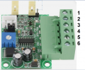
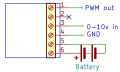
Probably like this, though the documentation is appalling :

1783456479930.png1783456819406.png

But you must set jumpers correctly for 10v input, 5v output, positive polarity.
 
Last edited:

panic mode

Joined Oct 10, 2011
5,179
also what you using as load? the larger DPAK unit is voltage regulator 7805 and not a power MOSFET. unlike many PWM modules out there, this one has small transistors as outputs and they cannot handle a lot... even if they are AO34xx, they are limited to some 24V, 4A, 1W . in other words, you may want to use it as a signal source for some device but to drive a load, this will likely need another stage...
 

panic mode

Joined Oct 10, 2011
5,179
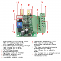
what is the voltage of your LiPo batteries? 7.4V (2x3.7)? if so you may want to try wiring it like this:
1783458524196.png

1. set jumper for 10V input.
2. set jumper for "24V" PWM output. that is not really 24V is it anything higher than 5V (input voltage or in your case 7.4V).
3. or 4. you can use one of the two outputs
5. this is where your 0-10V comes in
6. GND is known by many names including 0V or that would be your battery negative terminal potential.
7. this should turn on when battery power is applied.
8. battery negative (same as 6)
9. battery positive (7.4V)
10. this sets actual PWM frequency.
11. optional jumper(s) to invert PWM phase
12. this is possibly internally wired to terminal block 3 and 4 as marked by Irwing in post #3.
 

Irving

Joined Jan 30, 2016
5,195
I was keeping it simple for Eddy. Most RC ESCs, servos, etc, require a +ve going 5v pulse. Most of these devices usually run off a 7.4v LiPo pack, but the PWM standard is 5v, with a pulse width from 0.5 to 1.5mS, ie 25 - 75% duty cycle at 1KHz.
 
Top