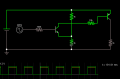
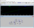
With the existing circuit:
0v - 0.7v = low
0.7v - 12v = high
This is heavily imbalanced, and I wanted to get the switching point closer to 6v so that I have just as much wiggle-room on both the low and high input levels.
Ideally:
0v - 6v = low
6v - 12v = high
Here is a circuit that uses only transistors and diodes to build a wall clock: http://transistorclock.com/index.html
The all transistor clock manual has also the circuits inside.
Here is a circuit that uses only transistors and diodes to build a wall clock: http://transistorclock.com/index.html
The all transistor clock manual has also the circuits inside.
That is far from ideal. The slightest noise superimposed on a signal very close to 6V would unintentionally flip the logic state from 0 to 1 or vice versa. See post #55 re noise margin.
Edit: If instead you defined low as, say, 0V-3V and high as 9V-12V, that would give you a good noise margin.
That is far from ideal. The slightest noise superimposed on a signal very close to 6V would unintentionally flip the logic state from 0 to 1 or vice versa. See post #55 re noise margin.
Edit: If instead you defined low as, say, 0V-3V and high as 9V-12V, that would give you a good noise margin.
That is fine also as far as im concerned.
My issue is that all testing with the circuits so-far has shown them switching at an input around 0.7v, which is way too low to be safe in my application. I need more room around the 0v level than just 0.7v.
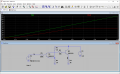
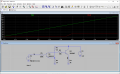
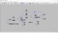
Ok, sorry about that. I swapped for PNP and this is what I get now. Vout now swings between 0 and 1.4v, but DOES do it around 6V, which is perfect. I think I just need to modify the output resistor to get the output up to 12V, will experiment with that next.
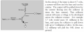
When Q1 turns on, it draws current through Q2's base-emitter junction (direction of base-emitter arrow) which turns it fully on, applying the supply voltage to R5.
Note that if you use a CTL R (rotate) and CTL E (mirror image) while moving Q2, you can rotate it with the emitter up to match post #63.
Ok, thanks.
Im a hobbyist, never had any classes in this stuff, so just trying to see what I can do.
Im new to LTspice also, so I didn't know any of the shortcuts, ill see if I can flip it over which might look better.
I think this circuit will work for what I want to build, really cool. Thanks for all the help guys.
I tried putting the little hand on the Q2, but CTRL-E didn't do anything. Does it only work when placing new components?

 Facebook
 Google
 GitHub
 Linkedin