 Facebook
 Google
 GitHub
 Linkedin
Hi
I have a problem with the fuel pressure regulation on my HDI diesel engine. After many hours of testing and replacing parts, I've come to the conclusion that there is a problem inside the ECU. The car is a banger, so it's not worth getting a new ECU, so I am trying to work out something to compensate for the fault.
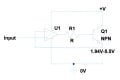
The pressure control regulator is fed on one side with a constant 14.3 volts, the output then goes to the ECU, which regulates the current flow according to demand from the accelorator. At low demand (and thus low current flow) there is no problem, but above about 1500mA it appears that the control circuitry inside the ECU just shorts momentarily (about 1/4 second) every few seconds, thus sinking maximum current through the pressure regulator causing the car to surge sporadicaly.
I first thought of using the original control circuit to power a transistor (a TIP120 I had lying around) which would reduce dramatically the current flowing through the ECU and maybe eliminating the problem (if it was due to overheating), but if not, I could adapt the circuit with a capacitor to eliminate the surges. I've now given up on that idea because of the problem of gain using a transistor, this would alter dramatically the current output to the pressure regulator with only a small demand in change from the ECU.
Next I thought of using a capacitor to smooth out the 'dips', but I would need a huge capacitor as at maximum demand there is over 2 amps flowing through the regulator. An inductor would work, but again, perhaps I would need a very large one to make any difference?
I could restrict the current flow by putting a relay or transistor in circuit, that above a certain current flow (or voltage to the regulator) it operated and disconnected the ECU and connected to earth via a resistor, but the problem with that is the resistor would have to be a fixed value, so depending on when it operated, I would still either get a surge, or drop off in power momentarily.
The figures I have measured are: Current flow: At idle - 750mA, driving steady uphill - 1400mA, foot to the floor - 2000mA. Voltage across regulator: At idle - 1.94V, driving steady uphill - 3.6V, foot to the floor - 5.5V. The Vcc is 14.3V, I've calculated the resistance of the regulator at 2.6 ohms.
Does anyone have any suggestions? (apart from scrap the car!)
I have a problem with the fuel pressure regulation on my HDI diesel engine. After many hours of testing and replacing parts, I've come to the conclusion that there is a problem inside the ECU. The car is a banger, so it's not worth getting a new ECU, so I am trying to work out something to compensate for the fault.
The pressure control regulator is fed on one side with a constant 14.3 volts, the output then goes to the ECU, which regulates the current flow according to demand from the accelorator. At low demand (and thus low current flow) there is no problem, but above about 1500mA it appears that the control circuitry inside the ECU just shorts momentarily (about 1/4 second) every few seconds, thus sinking maximum current through the pressure regulator causing the car to surge sporadicaly.
I first thought of using the original control circuit to power a transistor (a TIP120 I had lying around) which would reduce dramatically the current flowing through the ECU and maybe eliminating the problem (if it was due to overheating), but if not, I could adapt the circuit with a capacitor to eliminate the surges. I've now given up on that idea because of the problem of gain using a transistor, this would alter dramatically the current output to the pressure regulator with only a small demand in change from the ECU.
Next I thought of using a capacitor to smooth out the 'dips', but I would need a huge capacitor as at maximum demand there is over 2 amps flowing through the regulator. An inductor would work, but again, perhaps I would need a very large one to make any difference?
I could restrict the current flow by putting a relay or transistor in circuit, that above a certain current flow (or voltage to the regulator) it operated and disconnected the ECU and connected to earth via a resistor, but the problem with that is the resistor would have to be a fixed value, so depending on when it operated, I would still either get a surge, or drop off in power momentarily.
The figures I have measured are: Current flow: At idle - 750mA, driving steady uphill - 1400mA, foot to the floor - 2000mA. Voltage across regulator: At idle - 1.94V, driving steady uphill - 3.6V, foot to the floor - 5.5V. The Vcc is 14.3V, I've calculated the resistance of the regulator at 2.6 ohms.
Does anyone have any suggestions? (apart from scrap the car!)
") .
.


