Help with circuit to compensate for faulty ECU

Alec_t

Joined Sep 17, 2013
15,149
If you doubt Cork_ie, try feeding the ECU signal at tick-over via a capacitor (something in the 1oonF to 1uF range should do) to your meter set to read AC volts and report the reading. That should tell us if the signal is PWM or just DC.

Edit: set meter to AC volts, not DC
 
Last edited:

Thread Starter

Dumpster

Joined Feb 10, 2015
32
If you doubt Cork_ie, try feeding the ECU signal at tick-over via a capacitor (something in the 1oonF to 1uF range should do) to your meter set to read DC volts and report the reading. That should tell us if the signal is PWM or just DC.
Mmmm, funny you should say that, at one point, I did try connecting a large value capacitor across the regulator to try and smooth the signal out and the car didn't like it at all, it got all juddery and the capacitor got all hot and bothered. I couldn't understand why, as DC shouldn't be able to flow through a capacitor. Will try what you suggested, although I have to add that I don't doubt any advice given here, as I know very little about car electronics.
 

Thread Starter

Dumpster

Joined Feb 10, 2015
32
It is a PWM dignal controlled on the negative side by the ECU, As far as I remember the output driver is a mosfet or IGBT

Where is this coming from? The regulator is supplied with + Ign voltage via the main relay (12V-14V nom.) and grounded by the ECU
The DC resistance of the regulator coil is only about 1.5 Ohm. Fuel pressure is a function of engine load and speed. Can you try and graph rail pressure v's engine revs on a diagnostic computer,while driving the car? Again I repeat you really need to check this with a scope before going any further. Almost any half decent garage has them nowdays.
I do this kind of stuff all day every day and have worked on at least 500 of these engines in various cars and 4X4's and I have never seen the symptom you describe, caused by an intermittent short in the output driver of the ECU
What, your saying makes sense, it looks like that saying that my old college lecturer told me many years ago and has haunted me all my life, has reared it's ugly head yet again, "to assume, makes an ass out of U and ME!"

Graphing, diagnostic computers etc, is going to be next to impossible I'm afraid.

Almost any half decent garage has them nowdays.
That is the problem! I live in very rural Brittany in France. The local garage had it for 3 weeks, gave it back to me the same along with a 600 euro diagnostics bill. I took it to a "specialist" in our nearest city, he had it 2 weeks, shrugged his shoulders, "don't know what's up with it", but at least he didn't charge me. So, I don't have access to any decent diagnostic equipment. It's just me, my Fluke and a few electronics bits.

I wonder if you can turn a laptop into a scope with the right leads and software?

The values of voltage and current were all measured on DC, so if it is a PWM signal, they are not accurate.
 

Hymie

Joined Mar 30, 2018
1,347
It might be some heating effect causing the issue (since it takes 30 seconds or so for the problem to start), with the ECU unable to deliver the required current into the 2.6Ω load.

It should not damage anything trying my proposed circuit (thereby guaranteeing that the current can be supplied). If it does not work, you’ll need to seek an alternate solution – or scrap the vehicle.
 

Alec_t

Joined Sep 17, 2013
15,149
I've designed an alternative to Hymie's circuit, which should work for a PWM'ed regulator. Be warned, though, it's a lot more complicated and would benefit from a scope to set it up and tweak component values :). I'll post it if you're interested? It's designed to limit the duty cycle to some maximum value, to disconnect the ECU signal when it gets stuck at ground level, and to provide alternative pulses during the stuck state.
There are numerous apps available for using a PC soundcard as a scope for signals in the audio range, which the PWM is likely to be. You would need a potential divider to get the ECU signal down to 'line level' or 'microphone level' audio.
 
Last edited:

Thread Starter

Dumpster

Joined Feb 10, 2015
32
I've designed an alternative to Hymie's circuit, which should work for a PWM'ed regulator. Be warned, though, it's a lot more complicated and would benefit from a scope to set it up and tweak component values :). I'll post it if you're interested? It's designed to limit the duty cycle to some maximum value, to disconnect the ECU signal when it gets stuck at ground level, and to provide alternative pulses during the stuck state.
There are numerous apps available for using a PC soundcard as a scope for signals in the audio range, which the PWM is likely to be. You would need a potential divider to get the ECU signal down to 'line level' or 'microphone level' audio.
That would be great if you could post it, thanks, then I could take a look and see if I have the parts and/or capability to build it :). Thank you.
 

Alec_t

Joined Sep 17, 2013
15,149
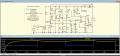
Here's a first draft :-
DutyCycleLimiterAndSubstitute.PNG
V(pwm) represents the duty cycle percentage. I(Lreg) is the regulator current.
SW models the ECU drive for the regulator. Providing SW is below the critical value, M1 is switched on. If SW gets stuck at maximum (100%), a missing pulse detector comprising D5/R6/C3/U1a turns off M1 via Q1, and turns on an oscillator comprising U1b/R9/C4/D8/Trimpot. The oscillator pulses drive Q2 and hence M2 and the regulator.
The Trimpot enables the oscillator pulse duty cycle to be selected to give a suitable limited regulator current while the stuck state exists.
I've attached the .asc file for the simulation.
 

Attachments

bwilliams60

Joined Nov 18, 2012
1,450
You can make a scope out of your cellphone. There are numerous google links on how to do it. ECUs are taken apart and I am assuming you are in the UK?
There are several places over there that do ECU repair work but the only thing that may cause your problem is a broken solder joint. Not unheard of but not sure on this unit. I mostly deal with NA vehicle ECMs so cant help you on where to look. As corkie pointed out, not likely to be an ECU internal component. Scope is best in this case as others have pointed out
 

Thread Starter

Dumpster

Joined Feb 10, 2015
32
OK, Thank you for the circuit Alec_t, looks like some work went into that! I very much appreciate it. I will have a think about how to source the components if I go ahead and build it, it used to be so easy to get hold of components when I lived in the UK, not so easy now.

Thanks bwilliams60, I will look into that. No, I'm no longer in the UK, that's part of the problem. You would think, Citroen being a French car, living in France would make it easier, but alas, no. The garages here just can't be bothered to spend the time diagnosing a tricky fault like this. Where I lived in the UK, just down the road was a Bosch diagnostics center - simples!
 

cork_ie

Joined Oct 8, 2011
428
You should be able to buy a used ECU for this for very small money from a French or British breakers yard. It is a very very common engine.
You can overcome the immobiliser either by,
1) Swap the eeprom (8 pin DIL ) from your own ECU
2) Make use of security flaw in system, start engine and disconnect immobiliser while engine running.
ECU is now "Open" and can be swapped from car to car as long as it cannot connect to an immobiliser.
You will be relying on the breakers yard to do this for you. Ensure your own immobiliser i disconnected as well.
This should be a far cheaper option than trying to make a complicated circuit which may or may not, sort your issue.
 

Thread Starter

Dumpster

Joined Feb 10, 2015
32
You should be able to buy a used ECU for this for very small money from a French or British breakers yard. It is a very very common engine.
You can overcome the immobiliser either by,
1) Swap the eeprom (8 pin DIL ) from your own ECU
2) Make use of security flaw in system, start engine and disconnect immobiliser while engine running.
ECU is now "Open" and can be swapped from car to car as long as it cannot connect to an immobiliser.
You will be relying on the breakers yard to do this for you. Ensure your own immobiliser i disconnected as well.
This should be a far cheaper option than trying to make a complicated circuit which may or may not, sort your issue.
Thank you cork_ie, I will ask around the local breakers to get an idea of the price. How would I go about identifying the eeprom chip amoung all the other chips?
 

bwilliams60

Joined Nov 18, 2012
1,450
The EEPROM chip is usually an 8 legged creature (IC), located somewhere on the circuit board. If you can post a clear picture of the board, we can tell you which one it is. Swap them and your immo should work.
 

cork_ie

Joined Oct 8, 2011
428
Thank you cork_ie, I will ask around the local breakers to get an idea of the price. How would I go about identifying the eeprom chip amoung all the other chips?
The eeprom is an 8 pin DIL ic . I think there are only three in the whole ECU, depends on the part no.of the ECU
One is a CAN Transceiver which is similar in appearance.
If you look at the part numbers on the ic you van verify the application here: https://www.alldatasheet.com/
 

Thread Starter

Dumpster

Joined Feb 10, 2015
32
Hello all

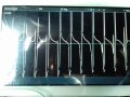
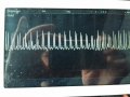
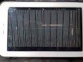
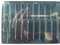
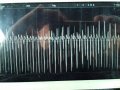
I have not had much time to investigate this much further due to other more urgent stuff, but during the week I made a make-shift oscilloscope with my tablet, a free app and some bits I had lying around. I have attached the traces (2 for each condition, different scope settings). Please bear in mind this was a zero cost setup, so not the most accurate readings. I was surprised to see that when the fault occurs, there is not a simple grounding of the signal, but rather what appears to be a largely amplified pulse. Could this still be a faulty ECU or do these traces discount that theory? Thanks again for all your inputs.

In Order the Images are Normal Idling 1 & 2, Normal Acceleration 1 & 2 and Fault Condition 1 & 2.

Idling Trace.jpg Idling Trace 2.jpg Normal Acceleration Trace.jpg Normal Acceleration Trace 2.jpg Faulty Condition Trace.jpg Faulty Condition Trace 2.jpg
 

cork_ie

Joined Oct 8, 2011
428
These look pretty good and the general pattern is what is expected. There is no sign of a short and you can more or less discount the theory of the ECU going short circuit pulling the regulator full on.
I would also expect fault codes for fuel pressure too high if that were the case.
Can you get someone with a diagnostic scanner to check for rail pressure V's engine RPM and see that the pressure rises with the rpm.
Nothing fancy is required. I don't know if your vehicle supports EOBD or not but if it does, a €60-00 handheld unit will do the job for you.
 

Thread Starter

Dumpster

Joined Feb 10, 2015
32
I don't know anyone with a diagnostic scanner I could borrow. However, when I first took the car to the garage with this fault, I was in the passenger seat holding the laptop, while the mechanic was driving and glancing over at the display. The rail pressure seemed to rise steadily ok with acceleration, but the problem was, it was a digital read-out, and the figures were changing so quickly, it was very difficult to follow. This is why, when I decided I had to sort this out myself, I measured the rail pressure directly from the pressure sensor, but with an analogue meter which gave a much clearer picture of what was happening (i.e. rail pressure increasing ok with demand, but spiking upwards every now and again). I don't know if his diagnostic software was capable of displaying rail pressure graphically, but if so, he didn't use that function. I can't go back and borrow that one, as we are not on good terms at the moment!

In a way, if what you are saying is true, it's bad news, as I am back to square one, trying to find a faulty component or sensor somewhere.
 
Top