Thread Starter

MyWaveformsHaveTeeth

Joined Sep 10, 2026
2
Hi, I'm looking to switch a single output between two analogue inputs. It needs to be voltage controlled, so I was looking at some ICs (CD4066, 74HC4053, etc) but I'm struggling to find one that doesn't implement more channels than I need while still being a through-hole configuration.

The inputs will be routed from guitar pedals, so will have up to ~3-4V peak to peak. What circuits are available to me to use for this purpose?

I've seen some reference online to MOSFET based switch circuits, but is there a configuration that would work with BJTs or OP-amps?
 

kiroma

Joined Apr 30, 2014
175
You can use a 4-pin MOSFET (bulk pin exposed) to make it as an analog switch. You just need to apply a Vgb>>Vth, so it remains conducting any signal. Just be sure you put a resistor in parallel with Vgb when you don't want it to be on anymore.
PNs are: SST211, SST213, SST215, MIC94050, MIC94051, MIC94030, MIC94031
I haven't checked them all, they are from another forum from more than a decade ago, so they might not be in production anymore.
Edit: they might not be PTH, as I haven't checked them. But as there aren't many 4-pin MOSFETs, you might have to consider SMT form. Maybe adapt to a PTH, making a PCB, it depends on your needs and expectations. But also you can search for other PNs. The direction is this.;)
 
Last edited:

panic mode

Joined Oct 10, 2011
5,205
This package is not through-hole.
you are missing out and paying too much. embrace SMD and start with larger packages like SOIC (1.27mm pitch).

https://www.mouser.ca/en/ProductDetail/Vishay-Siliconix/DG418BDY-T1-E3?qs=jcx%2B0HVgj2ZDzZxqgmGYog==

and if you like to practice, get few of them and breakout boards to turn this into DIP8 part.

note that above is SPDT.

the only small THT part that is in stock is TS12A4515P but... it is only SPST, so in your case one would need two of them, and an inverter.so what is the reason to avoid parts with multiple channels?

https://www.mouser.ca/en/ProductDetail/Texas-Instruments/TS12A4515P?qs=7kv20MEVUlj2WX1oKG9PWw==
 
Last edited:
I remember seeing this done with a pair of bipolar diff stages. To achieve sufficient isolation, the long-tailed pair must be very well matched. This means integrated devices. RCA solid state had a thru-hole IC for that purpose, but it has long been obsolete.

Therefore I join the chorus of people urging you to embrace SMT devices. SOIC packages are not difficult to solder. Advice that hopefully you won’t dismiss.
 
I thought the TS was not wanting to use a CD4066 or 74HC4053, because of size. But he then goes on to request a way of using discrete components which would take up more space. If he us a 4066 he would also need an inverter. I agree with BobTPH (post #5) that the 4053 can be used a 2 input muliplexer.
The analog signal must never go below ground level. Is the anolog signal just sound or something else ?
Would a small relay not do what you want ?
Les.
 

kiroma

Joined Apr 30, 2014
175
I thought the TS was not wanting to use a CD4066 or 74HC4053, because of size. But he then goes on to request a way of using discrete components which would take up more space. If he us a 4066 he would also need an inverter. I agree with BobTPH (post #5) that the 4053 can be used a 2 input muliplexer.
The analog signal must never go below ground level. Is the anolog signal just sound or something else ?
Would a small relay not do what you want ?
Les.
Relays for low current applications are not recommended, unless it's a solid-state relay. The contacts oxidize and start to not conduct with time.
 

crutschow

Joined Mar 14, 2008
38,752
4066 does not need inverter... it has extra channels, each can be used as inverter (just need pullup resistor...)
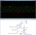
Below is the LTspice sim for that configuration to make a SPDT switch:

It shows three individual switches but they are all in one CD4066 package.
U3 is used as a logic inverter.
One switch is unused

Note that the signal level must be between 0V and Vdd.
If it's a ± AC signal around ground then it must be offset using resistors and capacitors to be centered at 1/2 Vdd.

The maximum pp input signal is ground to Vdd.

1789056467462.png

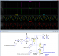
Edit: Alternately, if you have plus and minus voltage available, you could switch a ± AC signal without having to offset it (below):
Q1 and Q2 level translate the +V input control (purple trace), to the ±V signal (green trace) needed to switch the CD4066 when using dual supplies.
The peak-peak allowed signal level is Vdd to Vss.


1789064719807.png
 
Last edited:

AnalogKid

Joined Aug 1, 2013
12,260
I'm struggling to find one that doesn't implement more channels than I need
This has absolutely no effect on the chip's performance in your application. It is an unnecessary limitation of the field of acceptable components.

As long as the input impedances of the two analog inputs are relatively high (greater than 20K), the variation in switch on-state resistance with signal amplitude for the CD4066 should be small enough to be useful. Of course there are many analog switch chips to choose from that are newer, have way better distortion specs, and are "clickless". That is, the chip does not introduce a audible pop or click during its transition.

With a part like the 4066, two sections are the main audio switches, one section is configured as an inverter for the control signal, and one section is unused.

ak
 

kiroma

Joined Apr 30, 2014
175
This has absolutely no effect on the chip's performance in your application. It is an unnecessary limitation of the field of acceptable components.
He might be concerned with the current consumption, which will be inherently higher if the IC has more circuits to bias. Or he might want it to be just sufficient, no extra things, for example, to count the transistors used, idk, I've done such things before.
 
Top