Help with amplifier. Not amplifying as it should be.

Audioguru

Joined Dec 20, 2007
11,248
At 40kHz the lousy old LM358 has a gain of about 25 when its supply is 30V.
With a supply of only 10V to 15V then the gain is about 20.
With a supply of less than 10V then its gain at 40kHz is probably less.

The LM386 is a power amp with internal negative feedback for a gain of 20. It is -3dB at 300kHz. A capacitor can be added to increase its gain to 200 where it is -3dB at 35kHz.
 

Thread Starter

kris_maher

Joined Apr 24, 2009
90
I spoke with a lecturer of mine and he suggested I try for better OpAmps. Max bandwidth for the LM386 is 300kHz. So there shouldn't be a voltage limitation as I found out from the earlier opamp (thanks for waking me up).

I figured that since input voltage is 10mV p-p sine for an object that is at the maximum distance away from the tx/rx pair (1 metre. Yes I know that's kinda lame but if this works for the receiver I'll consider using this amplifier as the main driver for the transmitter as well) I use a gain of 50 first followed by another gain of 10 using a 2nd LM386. I can set the gain via resistor/capacitor pair at pins 1 and 8.

This should give me 5V p-p ac at the output. The supply voltage would be at 5V though.

There's no mention of slew rate however it says low distortion at 0.2%. What say? Good choice as a amplifier for receiver?
 
Last edited:

SgtWookie

Joined Jul 17, 2007
22,230
Kris, just a quick post ---

Sorry, I've been mighty busy the last couple of days.

SteveB's gotten you on the right track. I'd been looking at an ST Microelectronics datasheet for the LM358, which indicates a gbw of 1.1MHz; that translates to a maximum gain of 27.5 at 40kHz.

However, you're using a Texas Instruments LM358, whos' datasheet indicates a gbw of 0.7MHz; that translates to a maximum gain of 17.5 at 40kHz on a good day with a tailwind, figuratively speaking. This explains a large part of the discrepancy between the simulation and the real-world components.

The other part is the high output impedance of the sensor; that was not planned for in the simulation either. Under load, your sensor's output has decreased a great deal as you have observed (from 100mV down to 10mV). Increasing that load by changing the resistor from 10k down to 1k will result in more, not less load on your sensor's output - which will result in a lower p-p output from your sensor.

So, the first thing to do is to effectively decrease the output impedance of the sensor. This can be done by inserting a voltage follower (unity gain) stage between your sensor and the amplification portion. This will preserve the input signal's P-P voltage level so that it's not necessary to increase the gain.

Then the signal can be amplified. Keep in mind that it is not necessary to achieve a 5v p-p output; you can accomplish what you need to do with 1/5 that much gain. Attempting to achieve a square wave from the output of an opamp will require a considerable amount of bandwidth, which doesn't come cheaply.

The comparator stage is what will convert your sine wave into a 0v-5v square wave.

Keep ignoring Millwood's input. SteveB and Audioguru have given good replies.
 

Thread Starter

kris_maher

Joined Apr 24, 2009
90
Hi SgtWookie,

Does your comparator part of the circuit only work to convert the square wave if the voltage amplitude is at 2.5V ac (5V p-p)?

Since I have my own comparator circuit using LM311 on the transmitter, it relies on a 2.5V for a high and less than 2.5V for a low. It detects this via a square wave where there's a high and low naturally generated by the micro.

edit: I meant to say sine wave not square
 
Last edited:

SgtWookie

Joined Jul 17, 2007
22,230
Hi SgtWookie,

Does your comparator part of the circuit only work to convert the square wave if the voltage amplitude is at 2.5V ac (5V p-p)?
No, the comparator "looks at" the threshold above and below the median value (2.5v).

You can decrease that value by increasing the resistance in the feedback.

I have been busy for the last few days, and will be busy much of tomorrow, but I'll try to post a re-vamped circuit to compensate for the high input impedance of your sensor.

Keep ignoring millwood, that poster has nothing of value to contribute.
 

Thread Starter

kris_maher

Joined Apr 24, 2009
90
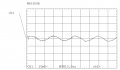
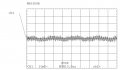
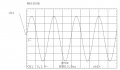
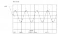
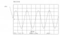
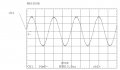
I took several samples yesterday in the lab. Both the output signals coming out of the Opamp circuit on the oscilliscope as well as the raw signal which is the signal between the sensor and the opamp circuit. As in:

Sensor --> Raw Signal on wire --> input to opamp circuit --> Opamp output

Here are the shots for some selected pics. BTW this is using the Murata tx/rx ultrasonic pair which proved to have a much greater range even though capacitances at 2000pF. The "MA40B8R" receiver and the Murata "MA40B8S" transmitter.

Also in the screenshots what I mean by "Default" is no object in front of the sensors. They're totally idle with no obstruction above them or around.

Eg. OUTPUT_1M means the output of the amplified signal of an object 1m away from the receiver sensor. Raw would mean the signal before entering the amplifier circuit.

Btw I didn't include the 1m range but for the raw signal it is just over 40mV p-p and at 1m coming out of the amplifier it is 100mV p-p. Also you can see the file name just hovering over the pictured attachment.

--------------------------------------------------------
Ok so the threshold value in the comparator can be decreased, so hence 5V p-p at the output of the opamp is not a must, it can be 4V p-p as well with the threshold at 2V.
 

Attachments

Last edited:

Thread Starter

kris_maher

Joined Apr 24, 2009
90
Yes it has a Av of 20 but it can be increased via a resistor/capacitor pair on pins 1 and 8. I'm sure a coupling capacitor would help. Also it won't have the BW problems as the previous amplifier has.

Or can you suggest a better Opamp? :)
 

SgtWookie

Joined Jul 17, 2007
22,230
You really don't need a better opamp it would appear; you have nearly 1v p-p output. Why not just set your thresholds for the comparator to be less than 1v?

What's the DC level that the output AC is riding on?
 
Last edited:

Thread Starter

kris_maher

Joined Apr 24, 2009
90
true but the 1v p-p is at the range of 2cm. It's not even 1m which is the range that the transmitter is sending the signal to. At 1m it's like 100mV p-p

The DC is at like around 3.1V (with the Murata tx/rx pair that have greater range). It's a straight line. It also fluctuates to become somewhat of a sine wave however its p-p amplitude is quite small when compared with the AC.
 

Attachments

SgtWookie

Joined Jul 17, 2007
22,230
Ok, so at what maximum range do you want to get an output?

That's where you need to read the p-p voltage value, so that we can start to figure out just what kind of gain you need. Earlier, we were going on 100mV p-p, but it appears that may not be what you're looking at.

Oh, the CA3130 has a GBW of 15MHz. That's more than 20x the gbw of the LM358 you have, and 50x better than the LM386. The LM386, like Audioguru implied, is not suitable for this project.
 

Thread Starter

kris_maher

Joined Apr 24, 2009
90
I'd say 1M is sufficient.

Yes I have the CA3130 (by Intersil) but have had a bad experience with it getting noisy every time I tested the receiver last semester or it could just be because I didn't know how to use it properly...As in a coupling capacitor etc.
 
Last edited:

steveb

Joined Jul 3, 2008
2,436
I'd say 1M is sufficient.

Yes I have the CA3130 but have had a bad experience with it going into saturation every time I tested the receiver last semester or it could just be because I didn't know how to use it properly...
It's very difficult to use that part on a protoboard. It's too hard to control parasitics and oscillations are difficult to eliminate without some tricks. You really need a good board layout and very careful design considerations for power supply filtering and feedback compensation.

You really don't need that part unless you are working at higher frequency. If you need more gain, just use multiple stages.

However, if you do find you become ambitious enough to use a CA3130, you can make a quick surface mount design using available surface mount adaptor PCBs. These little boards cost less than 10 dollars and would allow you to directly solder and connect SO8, SO14, 0805, 1206 and SOT23 packages and connect up even a 4 stage OPAMP design on a 1 in X 1 in circuit board. This would minimize parasitic inductance/capacitance and noise. You would benefit from small LC filters on the OPAMP power lines. Surface mount parts have a bad reputation for prototyping and experimental work, but I prefer them and have never had an issue with the packages mentioned above.
 

Thread Starter

kris_maher

Joined Apr 24, 2009
90
I guess I could give the CA3130 for another spin, I didn't put in a compensation capacitor between pins 1 and 8 last sem...

Also looking at:
http://www.picbasic.org/articles/ultrasonic/ultrasonic_experiments.html

This guy also uses lm358. He gets a gain of 100? I find that hard to believe since mine didn't appear to get a gain that high.

btw I plan on putting them on a board once Im done with all of this at the end, in the meantime a breadboard is quicker...
 

Audioguru

Joined Dec 20, 2007
11,248
The CA3130 can have high gain at 40kHz because you can reduce the value of its external frequency compensation capacitor. It is noisy.

The author used 100k and 1k gain resistors and wrongly believes his very slow LM358 has a gain of 100 at 40kHz. It is actually a gain of 100 at frequencies below about 2kHz.
 

Thread Starter

kris_maher

Joined Apr 24, 2009
90
Well if it's noisy it won't be a good option then? I basically need only a gain of 50 and then a gain of 10. So since its separate stages it shouldn't get noisy...
 

Thread Starter

kris_maher

Joined Apr 24, 2009
90
Ok guys I've decided to stick with the current receiver I have. I spoke with a teacher of mine and he said:

1) Don't use the lm386 it is noisy.
2) the GBW of the lm358 at 1mHz is not large enough to support high levels of gain so it's better to go for multi-stage.

3) Go for a lower gain than what I'm doing right now and see the output, then knowing that add a 2nd amplifier stage with an appropriate amount of gain you need but still keeping under the limit of the lm358.

4) Match the impedance of the sensor to that of the amplifier to get the best Vout possible. Ok now how can I do this?

Ok I just want to know a few things:

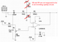
1) Currently the gain on the circuit is at 33? (R1 10k and R2 330k)? Well originally intended to be right?
2) What would be the purpose of the voltage divider R9/R10 in adjusting the gain? My teacher said he didn't think there's a reason for it to be there (ok on the simulation the Vout is reduced without the voltage divider there).

3) If the gain is only controlled by R1/R2 then if I were to reduce/increase these values to adjust the gain would the resistor values of R5/R4 need to be modified in any way?

4) In the comparator circuit (LM393), to decrease the threshold value from 2.5 to less (I could settle for 1.5V or 1V should be fine) I would increase the R7 value (feedback) and adjust the trimpot R12?

Sorry for the silly questions but I'm familiar with the standard amplifier circuits found in textbooks. I think this should take care of the receiver.
 
Last edited:

Thread Starter

kris_maher

Joined Apr 24, 2009
90
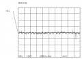
Ok I just added a few moments back a 2nd stage to the receiver. I have:

DC is at 4V flat line.

I made the gain of the 2nd stage amplifier (still using the same LM358) to be 24. After noting that (GBW = 1mHz) 1000000 / 40000 = 25 (maximum possible gain).

Since *after* amplification at the output of the 1st amplifier it is 100mV p-p (from the initial 10mv p-p) at 1 metre (less than 1 metre it's even better), so if the 2nd amplifier worked it would bump the 100mV p-p to around 2.4V p-p ac.

However instead I get a flat line in AC, and it is not responsive at all when an object is placed or moved on the top of the sensor as shown on the screenshot.

The 2nd amplifier is not like the one used in the 1st one (made by SgtWookie) but it's a basic one found in the text books without all the 'bells and wistles.' It's the basic non-inverting amplifier configuration using resistors R2/R1 for the gain. I used R2 as 36k and R1 as 1.5k to give a Av = 24.
 

Attachments

Audioguru

Joined Dec 20, 2007
11,248
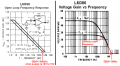
Look at the datasheet of the lousy old LM358:
1) There is a graph showing the Open Loop Voltage Gain.
Its GBW is 1MHz only if its supply is 30V.
Its GBW is only about 300kHz when its supply is from 10V to 15V.
Its GBW is probably less than 300kHz with your 5V supply.

2) There is a graph of Large Signal Frequency Response.
The max output at 40kHz is only 3V p-p when the supply is 15V.
Its max output is probably less than 3V p-p with your 5V supply.

You should not use R8 and R9 in your amplifier circuit.
The DC output of the opamp is adjusted with the pot R1 for symmetrical clipping.

The GBW of the LM386 power amplifier is 2MHz, not 300kHz.
Its cutoff frequency (-3db) is 300kHz when its gain is 20.
 

Attachments

Thread Starter

kris_maher

Joined Apr 24, 2009
90
Fair enough my teacher said the same about R8/R9, but SgtWookie had it on his receiver schematic??

But I could still use the LM358 right or should look for another?

The max output at 40kHz is only 3V p-p when the supply is 15V.
Would that be in AC p-p or DC?
 
Last edited:
Top