Facebook
 Google
 GitHub
 Linkedin
Hi everyone,
This is my first post on this website.
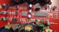
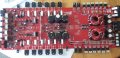
I am trying to fix a powerful car bass amp (Cerwin Vega CVP Series 1-Channel Class AB Monoblock Amplifier - CVP3000.1D) for my brother atm. The thing was switching on and off for a while and now doesn't seem to be switching on at all. There is 12V supply going in and I have put a jumper across to the REMote to switch it on (in theory!).
I seem to have whittled down the problem to no power coming into the Pulse Width modulator chip (a TL494CN). This should have Vcc (prob 12V) on pin 12 and atm there is 0V so I imagine there is no pulse signal going into the transformers for step up. (Please excuse me if my terminology is wrong - this is not really my area!).
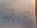
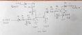
Unfortunately there seems to be no schematic for this device (very little for Cerwin Vega generally it seems). I have drawn out the area where I think the problem is (see photos) and would like to understand how this is supposed to work if anyone can help - so that we might be able to work out what has gone wrong. I have checked the resistor measurements and done diode tests on the transistors and diodes in situ and they seem to be fine.
This is my first post on this website.
I am trying to fix a powerful car bass amp (Cerwin Vega CVP Series 1-Channel Class AB Monoblock Amplifier - CVP3000.1D) for my brother atm. The thing was switching on and off for a while and now doesn't seem to be switching on at all. There is 12V supply going in and I have put a jumper across to the REMote to switch it on (in theory!).
I seem to have whittled down the problem to no power coming into the Pulse Width modulator chip (a TL494CN). This should have Vcc (prob 12V) on pin 12 and atm there is 0V so I imagine there is no pulse signal going into the transformers for step up. (Please excuse me if my terminology is wrong - this is not really my area!).
Unfortunately there seems to be no schematic for this device (very little for Cerwin Vega generally it seems). I have drawn out the area where I think the problem is (see photos) and would like to understand how this is supposed to work if anyone can help - so that we might be able to work out what has gone wrong. I have checked the resistor measurements and done diode tests on the transistors and diodes in situ and they seem to be fine.
Attachments
-
 167.1 KB Views: 16
 -
 476.9 KB Views: 14