 Facebook
 Google
 GitHub
 Linkedin
Hey all, I'm new to the forums and new to electronics. Please be gentle if I say or suggest anything completely boneheaded. 
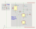
What I'd like to do is modify the switching behaviour of the "radio-button" circuit illustrated below such that a 2nd press of the SPST pushbutton disables the LED in its corresponding "block."
If we assume two "blocks"...
... the current switching behaviour is as follows:
If either BUTTON is activated, then activated a 2nd time, there is no change in the LED states.
The desired switching behaviour is as follows:
I am not concerned with the switching behaviour when two or more buttons are activated simultaneously.
I'm also not interested in MCUs or software. I was a software developer in a previous life. There's not much challenge left in that domain.
If you're wondering why half of the 4013 is sitting there unused it's because I want each "block" (excepting power, ground, and whatever logic/data lines are required) to be self-contained or "modular".
If there was such a thing as a single d-type flip flop in a DIP package, I'd be using it. But it appears that they're extinct.
Consequently, and as this self-contained/modular aspect is critical, the unused flip flop is fair game for any ideas that you might have.
As I'm new to this stuff I'm not sure how to approach this.
The software developer in me thinks I need only to track the button activations and send a pulse to the appropriate input. Something like:
Assuming that's a valid/wise/advisable approach, I'm unsure how to implement such a thing in hardware.
I was thinking a 2-bit ring counter using another 4013 -- where Q of the 1st bit goes to the SET input and Q of the 2nd bit goes to the RESET input -- but I've been unsuccessful in my attempts to breadboard this so far.
Any ideas/suggestions/solutions?
The end-game is to build an A/n audio input switcher (think A/B switcher but not limited to just A & B).
However, to begin learning how these components work, I thought it would be wise to start with just the switching behaviour. I don't want to get too deep too soon and frustrate myself any more than necessary.
Thanks much!
What I'd like to do is modify the switching behaviour of the "radio-button" circuit illustrated below such that a 2nd press of the SPST pushbutton disables the LED in its corresponding "block."
If we assume two "blocks"...
- Block A, containing
- BUTTON-01; and
- LED-01
- BUTTON-01; and
- Block B, containing
- BUTTON-02; and
- LED-02
- BUTTON-02; and
... the current switching behaviour is as follows:
- On power-up
- LED-01: disabled
- LED-02: disabled
- LED-01: disabled
- BUTTON-01 activated
- LED-01: enabled
- LED-02: disabled
- LED-01: enabled
- BUTTON-02 activated
- LED-01: disabled
- LED-02: enabled
- LED-01: disabled
If either BUTTON is activated, then activated a 2nd time, there is no change in the LED states.
The desired switching behaviour is as follows:
- On power-up
- LED-01: disabled
- LED-02: disabled
- LED-01: disabled
- BUTTON-01 activated
- LED-01: enabled
- LED-02: disabled
- LED-01: enabled
- BUTTON-01 activated a 2nd time
- LED-01: disabled
- LED-02: disabled
- LED-01: disabled
- BUTTON-02 activated
- LED-01: disabled
- LED-02: enabled
- LED-01: disabled
- BUTTON-02 activated a 2nd time
- LED-01: disabled
- LED-02: disabled
- LED-01: disabled
I am not concerned with the switching behaviour when two or more buttons are activated simultaneously.
I'm also not interested in MCUs or software. I was a software developer in a previous life. There's not much challenge left in that domain.
If you're wondering why half of the 4013 is sitting there unused it's because I want each "block" (excepting power, ground, and whatever logic/data lines are required) to be self-contained or "modular".
If there was such a thing as a single d-type flip flop in a DIP package, I'd be using it. But it appears that they're extinct.
Consequently, and as this self-contained/modular aspect is critical, the unused flip flop is fair game for any ideas that you might have.
As I'm new to this stuff I'm not sure how to approach this.
The software developer in me thinks I need only to track the button activations and send a pulse to the appropriate input. Something like:
Bad Pseudo-code:
$b1_count = 0;

while(true)
{
    if(true === $b1_activated) // BUTTON-01 has been pressed
    {
        switch($b1_count)
        {
            case 0:
            // send a HIGH signal to the SET input of U1A
            $b1_count = 1;
            break;
            case 1:
            // send a HIGH signal to the RESET input of U1A
            $b1_count = 0;
            break;
        }
    }
}I was thinking a 2-bit ring counter using another 4013 -- where Q of the 1st bit goes to the SET input and Q of the 2nd bit goes to the RESET input -- but I've been unsuccessful in my attempts to breadboard this so far.
Any ideas/suggestions/solutions?
The end-game is to build an A/n audio input switcher (think A/B switcher but not limited to just A & B).
However, to begin learning how these components work, I thought it would be wise to start with just the switching behaviour. I don't want to get too deep too soon and frustrate myself any more than necessary.
Thanks much!
Attachments
-
 124.5 KB Views: 10


