Facebook
 Google
 GitHub
 Linkedin

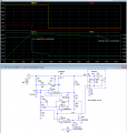
Below is the LTspice sim of my take on a lead-acid 12V, 2A constant-current battery charger, which drops to a trickle-charge voltage at the end of charge:
U2a limits the charge current to about 2.1A.
When the voltage reaches 14.5V (as determined by the U1 2.5V reference, and the values of R1 and R2 with R11 shorted to ground by M2), it goes into its constant-voltage, charge absorption mode.
When the current drops below 200mA (here at about 90s), U2b turns off MOSFET M2, which then adds R11 to the divider chain, and reduces the voltage to the trickle-charge value of 13.6V (here reached at about 150s).
The battery sim capacity value is low, so the charge time is greatly reduced compared to a real battery.
Note that the circuit has essentially a zero drop-out voltage (as determined by M1's on-resistance) so the input voltage can be as low as about 15V to minimize M1's dissipation, and the circuit will still charge normally.
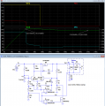
U2a limits the charge current to about 2.1A.
When the voltage reaches 14.5V (as determined by the U1 2.5V reference, and the values of R1 and R2 with R11 shorted to ground by M2), it goes into its constant-voltage, charge absorption mode.
When the current drops below 200mA (here at about 90s), U2b turns off MOSFET M2, which then adds R11 to the divider chain, and reduces the voltage to the trickle-charge value of 13.6V (here reached at about 150s).
The battery sim capacity value is low, so the charge time is greatly reduced compared to a real battery.
Note that the circuit has essentially a zero drop-out voltage (as determined by M1's on-resistance) so the input voltage can be as low as about 15V to minimize M1's dissipation, and the circuit will still charge normally.
Last edited: