What does the datasheet say on the matter? The Vgs(th) is minimum 2.0 V and maximum 4.0V. At that bias level you would not have a great deal of dynamic range. Check the characteristic curves for a suitable bias level. It is design for switching applications, so you may have a tiger by the tail when it comes to linear operation.
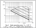
According to the SOA chart of the IRFZ44N, with VDS = 3.5V and a current of 3A, it is still within the safe operating area, right? Can it be run in linear mode, or do I need to find a linear MOSFET specifically designed for linear mode operation?
View attachment 370883±
According to the SOA chart of the IRFZ44N, with VDS = 3.5V and a current of 3A, it is still within the safe operating area, right? Can it be run in linear mode, or do I need to find a linear MOSFET specifically designed for linear mode operation?
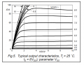
I wasn't thinking so much of SOA, but rather selecting the bias point and the signal swing about the bias point. For example, should it be 3.5V ± 1.5V or maybe 7.5V ± 3.5V. Where in the range of 2 to 20 volts do you want to operate? The graph you should be looking at is Id vs. Vds with Vgs as a parameter. Those curves will give you the answer.
Yes. All MOSFETs can operate in their linear mode. How long they can do it before expiring depends on their heatsinks.
At 4V x 3A, it will be dissipating 12W, which is well within the capability of the device provided that it is attached to a large enough piece of aluminium.
Thank you! My VGS applied during the linear sweep is 4.22V. Looking at the VGS and ID reference curves, at VGS = 4.22V, the ID current is very low, right? If the VGS voltage is high, the ID current is also high, right?
There is a ±1V tolerance on Vgs, so the drain current could be anywhere between what you read for 3.22V Vgs and what you read for 5.22V Vgs (and it varies with temperature)
It might be if the threshold is 4V, but if the threshold is 2V then it's well above.
You wouldn't operate a MOSFET in linear mode open-loop with no feedback.
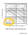
It is my experience; When a "classic" component becomes popular and becomes second sourced, the manufacturers which source it many times copy the original datasheet with errors, or simply change the original data. Thus I always like to find the original datasheet. Which I am reproducing below. What can you tell me about the parameters I circled in yellow, how do you plan on meeting them?
But since these curves are "typical" curves, you could still get lucky and find a device which survives your conditions.
Also my experience, when someone asks here if they can do "X", you'll always receive different opinions. Then, the person asking the original question will select whichever answer fits his desired outcome. Thus I am positive, as the sun will shine again tomorrow, that you will disregard any answers not meeting your confirmation bias. Please,This is NOT an attack on YOU, it is a comment on human nature. I most likely would do the same.
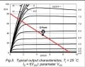
Using the drain characteristics from the datasheet I drew a potential load line for an amplifier circuit with a quiescent (Q-point) approximately halfway along the line. Like this
It looks like a Vgs of approximately 6.25 Volts and a Vgs swing of about ±1.25 V. Notice in particular you want to stay away from +4V where the device approaches cutoff and below 7.5 volts where you are approaching fully on with an rds(on) below 1Ω. I have no idea if you can realize a useful circuit with this device, but I am almost certain the results will be less than you expected.
We still don't know what the circuit is for to really help him.
If you place a transistor for purely linear mode, why don't place a resistor instead?
Maybe he wants to put a signal on its gate, but he didn't say for sure. We're left guessing. @AKFD , please give us more context.
We still don't know what the circuit is for to really help him.
If you place a transistor for purely linear mode, why don't place a resistor instead?
Maybe he wants to put a signal on its gate, but he didn't say for sure. We're left guessing. @AKFD , please give us more context.
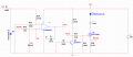
Resistor R2 is pulled up to the 16V supply, turning off Q1. Additionally, my design includes a mechanism where, when the battery is fully charged, it triggers R2 and Q3 to turn off Q1.

 Facebook
 Google
 GitHub
 Linkedin