Help me mosfet linear mode

crutschow

Joined Mar 14, 2008
38,724
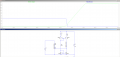
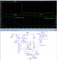
Below is the LTspice sim of my take on a lead-acid 12V, 2A constant-current battery charger, which drops to a trickle-charge voltage at the end of charge:

U2a limits the charge current to about 2.1A.
When the voltage reaches 14.5V (as determined by the U1 2.5V reference, and the values of R1 and R2 with R11 shorted to ground by M2), it goes into its constant-voltage, charge absorption mode.
When the current drops below 200mA (here at about 90s), U2b turns off MOSFET M2, which then adds R11 to the divider chain, and reduces the voltage to the trickle-charge value of 13.6V (here reached at about 150s).

The battery sim capacity value is low, so the charge time is greatly reduced compared to a real battery.

Note that the circuit has essentially a zero drop-out voltage (as determined by M1's on-resistance) so the input voltage can be as low as about 15V to minimize M1's dissipation, and the circuit will still charge normally.
1788405031980.png
 
Last edited:

Ian0

Joined Aug 7, 2020
13,243
I hope that this 60 mV you say is not 600 mV from the 0.41 ohm divided by 10. I imagine that you simulated that at least, or even calculated that Widlar to be this right.
But if it works as I understood your explanation, it's seems a good circuit.
This is the relevant part.Screenshot from 2026-09-02 19-51-26.png
 

Thread Starter

AKFD

Joined Apr 14, 2025
63
Below is the LTspice sim of my take on a lead-acid 12V, 2A constant-current battery charger, which drops to a trickle-charge voltage at the end of charge:

U2a limits the charge current to about 2.1A.
When the voltage reaches 14.5V (as determined by the U1 2.5V reference, and the values of R1 and R2 with R11 shorted to ground by M2), it goes into its constant-voltage, charge absorption mode.
When the current drops below 100mA (here at about 90s), U2b turns off MOSFET M2, which then adds R11 to the divider chain, and reduces the voltage to the trickle-charge value of 13.6V (here reached at about 185s).

The battery sim capacity value is low, so the charge time is greatly reduced compared to a real battery.

View attachment 370976
Thank you.
So, where in the circuit is the battery that needs charging?
 

crutschow

Joined Mar 14, 2008
38,724
Can I simulate it if I replace it with a 12V battery?
You can simulate it with that, but since a simulated 12V battery is an ideal voltage source which does not show a voltage change with current and acquired charge as a real battery does, so will not show the charging profile that my battery sim circuit does.

All you will see is a steady 12V output.
 
Last edited:

Thread Starter

AKFD

Joined Apr 14, 2025
63
You can simulate it with that, but since a simulated 12V battery is an ideal voltage source which does not show a voltage change with current and acquired charge as a real battery does, so will not show the charging profile that my battery sim circuit does.
So how do we calculate the simulation battery block?
 

crutschow

Joined Mar 14, 2008
38,724
I want to know what the voltage of the battery block is.
No voltage.
It acts as a simple battery that absorbs charge, with the voltage increasing linearly as it absorbs charge (a real battery would have a non-linear relation).
It's a very simple model to show how the circuit operates as the battery charges and its voltage increases.
In this case the circuit voltages are for a 12V lead-acid battery.
 

Thread Starter

AKFD

Joined Apr 14, 2025
63
No voltage.
It acts as a simple battery that absorbs charge, with the voltage increasing linearly as it absorbs charge (a real battery would have a non-linear relation).
It's a very simple model to show how the circuit operates as the battery charges and its voltage increases.
In this case the circuit voltages are for a 12V lead-acid battery.
Thank you.
By the way, can the TIP142 operate in linear mode?
VCE=6V IC=3A
 

crutschow

Joined Mar 14, 2008
38,724
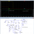
Below is the revised circuit using an op amp instead of the transistor differential stage to control M1, which performs the CC bulk, CV absorption, and CV float charge sequence:
It saves a few discrete parts, as the op amp can be part of a quad LM324 package.
It also should be be more accurate and temperature stable than the discrete differential stage.

LED D2 was also added to indicate the end of charge (start of float).

1788466582706.png
 
Last edited:

kiroma

Joined Apr 30, 2014
165
This question is unrelated to your circuit.
can the TIP142 operate in linear mode?
VCE=6V IC=3A
Beware of this power dissipation, if a heatsink is small, its thermal resistance will be higher than needed, thus it will heat up to a temperature that's not within the safe limits of the BJT. This topic is not that complicated for basic stuff, but it always requires a check, unless you use an overkill heatsink.
 

Thread Starter

AKFD

Joined Apr 14, 2025
63
Below is the revised circuit using an op amp instead of the transistor differential stage to control M1, which performs the CC bulk, CV absorption, and CV float charge sequence:
It saves a few discrete parts, as the op amp can be part of a quad LM324 package.
It also should be be more accurate and temperature stable than the discrete differential stage.

LED D2 was also added to indicate the end of charge (start of float).

View attachment 371003
Is the MOSFET M1 in your circuit operating linearly? I measured your circuit and the current is exactly 2A.
 

crutschow

Joined Mar 14, 2008
38,724
Is the MOSFET M1 in your circuit operating linearly? I measured your circuit and the current is exactly 2A.
Depends by what you mean by linear.
Technically the MOSFET is operating in its saturation region. It's regulating the bulk charging current at 2A.
A MOSFET's "linear' region is where the drain-source looks resistive, and the current is proportional to the drain-source voltage.

Why this continuing obsession about whether a device is in the "linear" region?
 
Last edited:
Top