Help me mosfet linear mode

kiroma

Joined Apr 30, 2014
160
View attachment 370912
This is my circuit. 12V battery charger circuit.
As @crutschow pointed out, the schematic has R2 tied to GND, and you said it's tied to 16 V (Vcc).
Another point I want to mention is that the SENSE point has a low-pass filter that's for a somewhat high frequency. Ok, I think, this is for filtering noise. But then comes a pure integrator with 10 nF of capacitance. I can't simulate it now, but from what I see and what I know, it should integrate the DC voltage it senses from R28 (current times 0.1 ohm) rapidly, and as it's inverting, it will drop the voltage at RD-A below the DC offset the non-inverting pin gives. Q3 doesn't invert as you might think. So, if it has current yet, after a certain point after starting, it will drop more the RD-A voltage. So it cuts off the MOSFET. That might be the cause you're thinking a switching MOSFET can't be used for linear application. But it isn't the cause.

I can be wrong in my train of thought, but maybe your circuit isn't suited for that application, ie. it needs modification to be able to operate it correctly.
 

Ian0

Joined Aug 7, 2020
13,243
View attachment 370912
This is my circuit. 12V battery charger circuit.
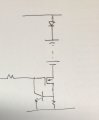
If you just want a constant current charger, then you don’t need the op-amp to set the current.
IMG_2404.jpeg
you will get approximately 0.6V/R. You can use the resistor attached to the MOSFET gate to switch it on and off (connect to V+ to switch it on) however, I don’t know of any batteries that are happy with a switched constant current charge - most like a constant voltage charge to finish.
And I would not delete D1, it stops the battery discharging through the charger circuitry if the power supply is switched off.
 

kiroma

Joined Apr 30, 2014
160
When it comes to replacing chargers, I refuse to build my own, more than a SMPS. SMPS you might need a custom one in your board, so you use all the manufacturer (of the IC) gives you, and even then you can have troubles. Chargers that are custom need to be validated through a lot of tests and a lot of time in production, to account for every possible outcome of problems. It seems simple, but it isn't.
 

WBahn

Joined Mar 31, 2012
33,089
I want to charge a 12V battery with a capacity from 7A to 20A.
Do you mean 7 Ah to 20 Ah? Ah and A are not remotely the same.

What type of 12 V battery? Lead acid, NiCd, Lipo, NiMH, ...?

The type is a major determiner in how you can/should charge it.
 

Thread Starter

AKFD

Joined Apr 14, 2025
59
Ý bạn là từ 7 Ah đến 20 Ah? Ah và A hoàn toàn không giống nhau.

Loại pin 12V nào vậy? Pin axit chì, pin NiCd, pin LiPo, pin NiMH, ...?

Loại thiết bị là yếu tố quyết định chính đến cách bạn có thể/nên sạc nó.
Lead acid
 

crutschow

Joined Mar 14, 2008
38,720
The charge current for a lead-acid battery should not exceed 30% of the Ah rating, so for a 7Ah battery, the charge current should be no greater than 2.1A.
Is that sufficient for charging the range of Ah ratings you want?

Do you need to drop the charge voltage to a trickle-charge value after it is charged, or will you disconnect the battery soon after it's charged?
 
Last edited:

Thread Starter

AKFD

Joined Apr 14, 2025
59
The charge current for a lead-acid battery should not exceed 30% of the Ah rating, so for a 7Ah battery, the charge current should be no greater than 2.1A.
Is that sufficient for charging the range of Ah ratings you want?

Do you need to drop the charge voltage to a trickle-charge value after it is charged, or will you disconnect the battery soon after it's charged?
Starting at 11.8V with a 2A current, the current then tapers down as it approaches full charge, and shuts off when it reaches 14.4V.
 

Ian0

Joined Aug 7, 2020
13,243
Starting at 11.8V with a 2A current, the current then tapers down as it approaches full charge, and shuts off when it reaches 14.4V.
But it’s not charged when it reaches 14.4V. That’s only the BEGINNING of the absorption charge phase. It needs to be kept at 14.4V until the current falls below C/20
 
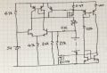
If all-transistor circuits are your thing, then try this one. View attachment 370956
I‘m sure Mr. Heath-Robinson would approve
Can you explain what the very right side does? It's a current mirror that takes the voltage at that 0.41 ohm resistor, which will be in the range of Vcc minus 0-600 mV, drops 2 diodes of 0.7 V, and that's the voltage over 22 kOhm. This current is mirrored to the right side, but it's a Widlar mirror, ok. But then you take the voltage of the current mirror and feed into the gate of BS170? I don't get it.
 

Ian0

Joined Aug 7, 2020
13,243
Can you explain what the very right side does? It's a current mirror that takes the voltage at that 0.41 ohm resistor, which will be in the range of Vcc minus 0-600 mV, drops 2 diodes of 0.7 V, and that's the voltage over 22 kOhm. This current is mirrored to the right side, but it's a Widlar mirror, ok. But then you take the voltage of the current mirror and feed into the gate of BS170? I don't get it.
The current in the current mirror (Vboost-2Vbe)/22k gives a voltage across the 100Ω resistors of about 60mV.
It compares the voltage across the MOSFET's source resistor with that 60mV. If it is greater, it switches the BS170 on, increasing the gain of the circuit so that the output is 14.7V. When the circuit reaches Absorption voltage and the current has fallen to C/50 (I bulk/10) the BS170 switches off and the circuit reverts to the lower gain setting the output to the float voltage of 13.6V.
 

kiroma

Joined Apr 30, 2014
160
The current in the current mirror (Vboost-2Vbe)/22k gives a voltage across the 100Ω resistors of about 60mV.
It compares the voltage across the MOSFET's source resistor with that 60mV. If it is greater, it switches the BS170 on, increasing the gain of the circuit so that the output is 14.7V. When the circuit reaches Absorption voltage and the current has fallen to C/50 (I bulk/10) the BS170 switches off and the circuit reverts to the lower gain setting the output to the float voltage of 13.6V.
I hope that this 60 mV you say is not 600 mV from the 0.41 ohm divided by 10. I imagine that you simulated that at least, or even calculated that Widlar to be this right.
But if it works as I understood your explanation, it's seems a good circuit.
 
Top